
Operating instructions


6
SECTION I — GENERAL INFORMATION
1. GENERAL INFORMATION
The boiler is designed specically for forced draft ring,
is available with oil, gas or combination gas/oil burners,
and operates with a combustion efciency of over 80%.
This manual gives the necessary information for the
proper installation, operation, maintenance and service of
units. For special installation problems, contact Burnham
Commercial, P.O. Box 3939 Lancaster, PA 17604, Phone:
888-791-3790 .
2. INSPECT SHIPMENT carefully for any signs of
damage.
A. All Equipment is carefully manufactured,
inspected and packed. Our responsibility ceases
upon delivery of boiler to the carrier in good
condition.
B. Any Claims for damage or shortage in shipment
must be led immediately against the carrier by
the consignee. No claims for variances from, or
shortage in, orders will be allowed by the
manufacturer unless presented within sixty
(60) days after receipt of goods.
3. SETTING THE UNIT
Most boilers are equipped with lifting lugs to be used
in maneuvering the boiler into position. On large boilers,
where four lifting lugs are supplied, all four lugs should be
used when lifting the boiler. Scotch boilers can also be rolled
into position using roller skids under the leg supports, pipe
rollers may cause damage. The unit should be located in the
boiler room so as to provide ease of venting and adequate
clearance for maintenance, serviceability and installation
of piping.
The tube pull space listed in the Burnham Commercial
product catalog must be provided at the front of the boiler.
The coil pull space must be maintained at the front of units
equipped with tankless coils. Floor construction should
have adequate load bearing characteristics to bear the
weight of the boiler lled with water. A boiler foundation
is recommended if the boiler room oor is weak, uneven
or if a water condition exists. These boilers are not for
installation on combustible ooring. If desiccant package
was ordered, be sure to remove from the boiler furnace
using the rear access, and from the waterside using the
manhole cover.
4. CHIMNEY OR VENT
On installations where a natural draft stack is used,
causing high breeching drafts, the boiler locking blade
damper (on boilers equipped with one) may require
adjusting, or one may need to be installed at the boiler
breeching. In multiple boiler installations, or in installations
where the breeching draft may vary considerably, automatic
draft controls in combination with a motorized damper may
be required.
When considering the stack and breeching, the design
should take into account that the boiler/burner combination
will work best when the pressure at the boiler ue outlet is
in the range of + or - 1/10 inch WC.
5. AIR SUPPLY
A sufcient air supply must be maintained at all times
to the boiler room for proper performance of the unit. A
permanent opening or duct should be provided so that
the boiler input will not exceed 4,000 Btuh/in
2
of free area.
Example: Firing Rate (Gas) = 528 MBH
528,000 BTUH = 132 In
2
Free Area
4,000 BTUH/In
2
Follow local building codes if they exceed these minimum
requirements.
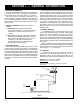
FRONT
OF
BOILER
SMOKEPIPE - DO NOT REDUCE BELOW
SIZE OF COLLAR ON REAR
SMOKEBOX
THIMBLE
FIGURE 1
TYPICAL ARRANGEMENT FOR STUB VENT
TS-71-129-B