
Operating instructions


@
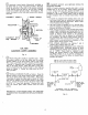
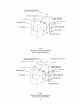
INSTALLATION OF TRIM AND CONTROLS
FOR WATER BOILERS. (See Figure
4
for Control
Locations.)
a. Screw COMBINATION ALTITUDE GAUGE AND
THERMOMETER into
%"
tapping. Tighten by
wrench applied to square shank back of gauge. DO
NOT APPLY PRESSURE ON GAUGE CASE since
this may destroy calibration of gauge.
b. RELIEF VALVE-Install in
1"
Tapping next to
3"
Supply Tapping in Front Section using fittings pro-
vided.
CAUTION
:
Safety Relief Valve should be piped to
and open drain-full size of discharge outlet on
Relief Valve and without any provision of "shut-off"
between the Relief Valve and discharge into drain.
c. Install Hydronic
Controls in their designated tap-
pings.
@
INSTALLATION OF TRIM AND CONTROLS
FOR STEAM BOILERS. (See Figure
4
for control
locations.)
a.
Screw Combination Pressure Vacuum Gauge into
designated
$"
tapping. Tighten by wrench applied
to square shank on back of gauge. Do not apply
pressure on gauge case since this may destroy cali-
bration
of gauge.
b. SAFETY VALVE. Install in
1"
Tapping next to
3"
Supply Tapping in Front Section.
CAUTION: Safety Valve should be piped to an
open drain-full size of discharge outlet on Safety
Valve and without any provision of "shut-off" be-
tween the Safety Valve and discharge into drain.
c. Install Pressure Limit Control with
1/4"
Pig Tail
Syphon into Heater Cover Plate Tapping bushed
3/4"
to
G".
d. Install Operating Control (supplied with Tankless
Heater equipped boilers only) in designated tapping.
e. Install Gauge Glass and Low Water Cut-off (if fur-
nished) in
y2"
tappings on left side of Front Sec-
tion.
@)
INSTALL SMOKEPIPE so that connection
to
Chimney or vent is short and direct.
a. Install in accordance with LOCAL FIRE ORI-
NANCES.
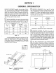
b. Smokepipe must not be smaller than the
8"
dia. flue
collar. See Fig.
1.
For Stub Vent installation see Fig.
3,
if connected
to chimney.
c. Do not connect into same leg of Chimney serving an
open fireplace.
d. Inspect Chimney for obstructions or restrictions
which should be removed. Clean Chimney if neces-
sary.
e. Smokepipe should slope upward from Boiler to
Chimney not less than one inch in four feet. Smoke-
.
pipe must be securely supported so as to maintain,
proper clearances from combustible materials and
to prevent separation of joints.
f. Insert Smokepipe into but not beyond inside wall of
Chimney Flue Lining. Pipe should be installed
above the extreme bottom of Chimney so as to pre-
vent stoppage.
y.
Seal between Smokepipe and Chimney connection to
prevent draft leakage.
0
INSTALL ROOM THERMOSTAT on an inside
wall about four feet above floor.
Never install Thermo-
stat on an outside wail or where it will be influenced by
drafts, hot or cold water pipes, lighting fixtures, tele-
vision, rays of the sun, or near a fireplace. Keep large
furniture away from Thermostat so there will be free
movement of room air around this Control.
@
OIL BURNER INSTALLATION. Bolt burner to
mounting plate with nuts and washers packed in boiler
parts carton. REFER TO BURNER INSTALLATION
and SERVICE MANUAL form No.
52004.
I
\
@)
BOILER with JACKET EXTENSION refer to
Figure
10
for assembly instructions.
h
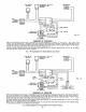
INSTALL ELECTRIC WIRING in accordance with
NATIONAL ELECTRICAL CODE and Local Regula-
tions.
a.
A separate ELECTRICAL CIRCUIT should be run
from Meter with a Fused Disconnect Switch in
this Circuit.
See Figures
11
thru
17
for appropriate wiring dia-
gram.