IN S TAL L AT ION , OP E R AT IN G AN D S E R V IC E IN S T R U C T ION S F OR V 8 H ™ S E R IE S OI L - F I R E D BOI L E R 9700609 F o r s e rvi c e o r re p a i r s to b o i le r, c a ll yo ur he a ti ng c o ntr a c to r o r o i l s up p li e r. W he n s e e k i ng i nfo rma ti o n o n b o i le r, p r o vi d e B o i le r Mo d e l Numb e r a nd S e ri a l Num b e r a s s ho wn o n Ra ti ng L a b e l lo c a te d o n to p o f the b o i le r.
IMPORTANT INFORMATION - READ CAREFULLY All boilers must be installed in accordance with National, State and Local Plumbing, Heating and Electrical Codes and the regulations of the serving utilities. These Codes and Regulations may differ from this instruction manual. Authorities having jurisdiction should be consulted before installations are made. In all cases, reference should be made to the following Standards: A. B. C. D. A. B.
DANGER DO NOT store or use gasoline or other flammable vapors or liquids in the vicinity of this or any other boiler. WARNING Improper installation, adjustment, alteration, service or maintenance can cause property damage, personal injury or loss of life. Failure to follow all instructions in the proper order can cause personal injury or death.
WARNING This boiler contains very hot water under high pressure. Do not unscrew any pipe fittings nor attempt to disconnect any components of this boiler without positively assuring the water is cool and has no pressure. Always wear protective clothing and equipment when installing, starting up or servicing this boiler to prevent scald injuries. Do not rely on the pressure and temperature gauges to determine the temperature and pressure of the boiler.
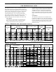
SECTION I: PRODUCT DESCRIPTION, SPECIFICATION AND DIMENSIONAL DATA circulator relays and adds energy saving thermal purge features. Energy is saved by starting the circulator and delaying the burner start when there is residual heat available in the boiler. A Warm Start Intelligent Oil Boiler Control (Warm Start Boiler Control) is included with a tankless heater option to generate domestic hot water.
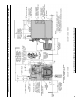
Figure 1A: V8H3 thru V8H9 Water Boiler without Tankless Heater SECTION I: PRODUCT DESCRIPTION, SPECIFICATION AND DIMENSIONAL DATA (continued)
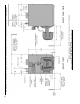
Figure 1B: V8H3 thru V8H9 Water Boiler with Front Tankless Heater SECTION I: PRODUCT DESCRIPTION, SPECIFICATION AND DIMENSIONAL DATA (continued)
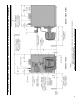
Figure 1C: V8H3 thru V8H9 Water Boiler with Rear Tankless Heater SECTION I: PRODUCT DESCRIPTION, SPECIFICATION AND DIMENSIONAL DATA (continued)
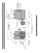
Figure 1D: V8H3 thru V8H9 Steam Boiler with or without Tankless Heater SECTION I: PRODUCT DESCRIPTION, SPECIFICATION AND DIMENSIONAL DATA (continued)
Section Ii: PRE-INSTALLATION A. INSPECT SHIPMENT carefully for any signs of damage. 1. All equipment is carefully manufactured, inspected and packed. Our responsibility ceases upon delivery of crated boiler to the carrier in good condition. 2. Any claims for damage or shortage in shipment must be filed immediately against the carrier by the consignee. No claims for variances from, or shortage in orders, will be allowed by the manufacturer unless presented within sixty (60) days after receipt of goods. B.
Section II: PRE-INSTALLATION (continued) C. PROVIDE COMBUSTION AND VENTILATION AIR. Local and National Codes may apply and should be referenced. WARNING Adequate combustion and ventilation air must be provided to assure proper combustion and to maintain safe ambient air temperatures. Do not install boiler where gasoline or other flammable vapors or liquids, or sources of hydrocarbons (i.e. bleaches, fabric softeners, etc.) are used or stored. 1. Determine volume of space (boiler room).
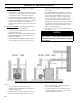
Section III: KnockDown Boiler Assembly A. REMOVAL OF BARE BOILER FROM SKID 1. Boiler is secured to skid with 4 bolts, 2 in front and 2 in rear of shipping skid, see Figure 3. Remove all bolts. G. INSTALL AND SECURE CANOPY with gasket and hardware provided to ensure gas tight seal — see Figure 4. Figure 3: Knockdown Boiler Removal from Skid 2. Tilt boiler to right and to rear. Using right rear leg as pivot, rotate boiler 90° in a clockwise direction, and lower left side of boiler to floor.
Section III: KnockDown Boiler Assembly (continued) Figure 5: Boiler Tapping Locations and Usage (Knockdown Boilers Only) PURPOSE OF TAPPINGS Tapping Location * Size NPT A ¾" B ¼" C ¾" C-C ¾" D ½" F ¾" G H J K 1½" 1½" 1½" 2" L 2" M ¾" Steam Boiler Non-Heater Water Boiler w/Heater Pressure Limit (Probe LWCO) Plugged (Float LWCO) Pressure Gauge Probe LWCO Std.
Section III: KnockDown Boiler Assembly (continued) Figure 6: Knockdown Boiler Jacket Assembly H. INSTALL TRIM. The following steam or water trim 2. Install jacket rear panel support bracket. (See will be concealed or inaccessible after boiler jacket is Figure 6, Item 2A). Align bracket with two (2) installed, see Figure 5 for boiler tapping locations and 5/16"-18 tapped holes in rear section and secure usage. with two (2) 5/16"-18 x 1/2" long cap screws. 3. Install jacket rear panel.
Section III: KnockDown Boiler Assembly (continued) Figure 7: Oil Burner Installation (Beckett Burner Shown) 6. Install jacket top panel. (See Figure 6, Item 2F). Place jacket top panel on boiler and secure to front, rear and left side panels with #8 x ½” long sheet metal screws. 7. Install jacket right side access panel. (See Figure 6, Item 2G). Align right side panel mounting holes with front and rear panel holes. Secure with #8 x ½” long sheet metal screws. 8.
Section III: KnockDown Boiler Assembly (continued) NOTICE When securing burner swing door make sure door is drawn-in equally on both sides. Step 3. Use a hand wrench to tighten door hardware and always start with the right side flange nut first (see Figure 13B). Use an alternating tightening method from right side flange nut to left side flange bolt to tighten door equally until sealed without applying excessive torque.
Section III: KnockDown Boiler Assembly (continued) 7. Inspect oil nozzle, electrodes and head setting. a. Installation/Removal of Drawer Assembly i. Loosen screws, rotate latches and swing open the transformer. ii. The combustion head assembly can be removed with the blower wheel access cover in place or removed. If the access cover is removed, the head assembly will not have to be rotated. Disconnect the flared fitting to the oil line and remove the aluminum thumb-nut from the nozzle line.
Section III: KnockDown Boiler Assembly (continued) iii. Re-install the combustion head assembly into the air tube. It may be necessary to turn nozzle line assembly upside down to ease insertion into the air tube. Then the threaded adapter on the end of the nozzle line is passed through the opening in the left side of the housing. iv. Run the aluminum (knurled) thumb-nut onto the nozzle line and tighten hand-tight. v. Connect the flared fitting on the copper oil line to the nozzle line and tighten. vi.
Section III: KnockDown Boiler Assembly (continued) If nozzle needs replacement, follow steps below Also refer to Figure 7C. i. Remove the nozzle adapter (2) from the drawer assembly by loosening the screw (1). ii. Remove existing nozzle from nozzle adapter. iii. Insert the proper nozzle into nozzle adapter and tighten securely (Do not over tighten). iv. Replace adapter, with nozzle installed, into drawer assembly and secure with screw (1).
Section III: KnockDown Boiler Assembly (continued) WARNING: Do not operate a single line system with the by-pass plug installed. Operating a single line system with the by-pass plug installed will result in damage to the pump shaft seal. NOTE: Pump pressure was factory pre-set but must be checked at time of burner start-up. A pressure gauge is attached to the PRESSURE/ BLEEDER PORT (7) for pressure readings.
Section III: KnockDown Boiler Assembly (continued) Figure 8: Limit Sensor Insertion 6. After control is installed and secured, remove control cover. Then, remove knockout located directly above factory connected limit harness on right side flange of control. Insert circulator harness end with attached fork terminals thru knockout hole and push-in to engage harness connector into flange. Connect wires to control terminals as follows - Blue to C1 and White to C2 and tighten securely. Reinstall control cover.
Section III: KnockDown Boiler Assembly (continued) Figure 9: Float-Type Low Water Cut-Off and Pressure Limit Installation 5. Install float-type LWCO, if so equipped. See Figures 5 and 9. a. Install nipples and unions in "D" Tappings. b. Mount hardware to low water cut-off body. Install assembly. c. Install water gage glass on low water cut-off assembly's tee fittings. 6. Install Pressure Limit Control. a. Float LWCO only: Remove ¼" NPT plug from top of Low Water Cut-Off.
Section III: KnockDown Boiler Assembly (continued) c. Refer to Paragraph R for details on use of burner disconnect junction box provided with all knockdown boiler builds. Q. INSTALL TRIM AND CONTROLS WITH RIELLO BURNER. Water Boilers Only (see Figures 1A, 1B, 1C and 5). Follow instructions in Paragraph N, Steps 1 through 7. Steam Boilers Only (see Figures 1D and 5). Follow instructions in Paragraph O, Steps 1 through 6. 7. Connect Field Wiring a.
Section III: KnockDown Boiler Assembly (continued) If you are using a burner with the disconnect harness, complete the following assembly instructions for mounting the mating burner disconnect junction box, see Figure 11. 1. Remove (2) #6 x 1/2" lg. machine screws and J-box cover from junction box. 2. Secure 2" x 4" junction box to jacket front panel with (2) #8 x 3/8" lg. sheet metal screws using prepunched holes below tridicator or pressure gauge tapping. 3.
SECTION IV: PACKAGED BOILER ASSEMBLY (continued) Figure 13A: Partial Front View - Burner Swing Door Mounted to Boiler - Fully Closed and Secured Step 4. From this position the door can be swung clear of the vertical circulator return piping to provide full access to the combustion chamber and burner head (see Figure 13B, Position 3). 2. Perform routine inspection, service or cleaning as necessary. 3. To close Burner Swing Door (see Figures 13A and 13B): Step 1.
Figure 13B: Top View - Burner Swing Door Mounted to Cast Iron Block Assembly (Jacket Removed for Clarity) SECTION IV: PACKAGED BOILER ASSEMBLY (continued)
SECTION IV: PACKAGED BOILER ASSEMBLY (continued) 3. Inspect ceramic rope located on the swing door. The rope must be evenly distributed around the perimeter of the door groove and cannot bunch or overhang. There must not be a gap where the two ends of the rope meet. Repair or replace if the rope is damaged or if there is a gap between the ends. F. INSTALL BECKETT OIL BURNER. Refer to Section III, Paragraph J for burner installation instructions.
SECTION V: WATER Boiler PIPING AND TRIM NOTICE Failure to pipe boiler as specified in this manual may result in excessive system noise, water line fluctuations and water carry over. A. EVALUATE THE EXISTING WATER SYSTEM. Design a piping system and install boiler which will prevent oxygen contamination of boiler water and frequent water additions. 1. There are many possible causes of oxygen contamination such as: a. Addition of excessive make-up water as a result of system leaks. b.
SECTION V: WATER Boiler PIPING AND TRIM (continued) 6. If it is required to perform a long term pressure test of the hydronic system, the boiler should first be isolated to avoid a pressure loss due to the escape of air trapped must first be removed from the boiler. To perform a long term pressure test including the boiler, ALL trapped air must first be removed from the boiler. A loss of pressure during such a test, with no visible water leakage, is an indication that the boiler contained trapped air.
Figure 15A: Recommended Water Piping for Circulator Zoned Heating System - Supply Side Circulators SECTION V: WATER Boiler PIPING AND TRIM (continued)
Figure 15B: Recommended Water Piping for Zone Valve Zoned Heating System ‑ Supply Side Circulator SECTION V: WATER Boiler PIPING AND TRIM (continued)
SECTION VI: STEAM Boiler PIPING AND TRIM WARNING Failure to properly pipe boiler may result in improper operation and damage to boiler or structure. Do not increase steam boiler input above the ratings. Do not use softened water in steam boilers. Accelerated boiler corrosion will result. Tie in fresh water supply to the boiler upstream of a water softener. Oxygen contamination of boiler water will cause corrosion of iron and steel boiler components, and can lead to boiler failure. U.S.
Figure 16: Recommended Boiler Piping for Gravity Return Steam Boiler Failure to pipe boiler as specified in this manual may result in excessive system noise, water line fluctuations and water carry over.
SECTION VII: TANKLESS AND Indirect Water HEATER PIPING A. CONNECT TANKLESS HEATER PIPING as shown in Figure 17A. See Tables 2A and 2B for Tankless Heater Rating. WARNING Install automatic mixing valve at tankless heater outlet to avoid risk of burns or scalding due to excessively hot water at fixtures. Adjust and maintain the mixing valve in accordance with the manufacturer's instructions. Do not operate tankless heater without mixing valve.
SECTION VII: TANKLESS AND Indirect Water HEATER PIPING (cont'd) Figure 17A: Schematic Tankless Heater Piping Table 2A: TANKLESS HEATER DATA: Rear Mounted Heater on Steam and Water Boilers Boiler Heater Model No. V8H3 V1-2 Heater Rating (GPM) Table 2B: Tankless Heater Data: Front Mounted Heater on Water Boilers Pressure Drop thru Heater (PSI) Boiler Model Heater No. Heater Rating (GPM) Pressure Drop thru Heater (PSI) Steam Water Steam Water V8H3 222B 3.00 18.7 2.75 3 3.9 4.
SECTION VII: TANKLESS AND Indirect Water HEATER PIPING (cont'd) Figure 17B: Indirect Domestic Water Heater Piping with V8H Steam Boiler B. CONNECT INDIRECT DOMESTIC WATER HEATER PIPING as shown in Figure 17B. 1. Refer to Indirect Water Heater Installation, Operating, and Service Instructions for additional information.
SECTION VIII: VENTING AND AIR INTAKE PIPING A. GENERAL VENTING GUIDELINES 1. Vent system installation must be in accordance with these instructions and applicable provisions of local building codes. Contact local building or fire officials about restrictions and installation inspection in your area. 2. The V8H is designed to be vented into a fireclay tile-lined masonry chimney or chimney constructed from type L vent or a factory built chimney that complies with the type HT requirements of UL103.
SECTION VIII: VENTING AND AIR INTAKE PIPING (continued) Figure 18: Recommended Vent Pipe Arrangement and Chimney Requirements 38 Figure 19: Proper and Improper Locations of Draft Regulator
SECTION VIII: VENTING AND AIR INTAKE PIPING (continued) 2. After determining location, cut a hole in the wall to accept 4 inch air intake pipe. See Figure 20. 3. Remove the metal knockout in right side of burner cover. Install U.S. Boiler Company Inlet Air Accessory Kit, P/N 611280031. 4. Mount the Vacuum Relief Valve Tee Assembly (P/N 8116268 included with Kit) or 90° elbow into the burner inlet ring. See Figure 20. a.
SECTION IX: ELECTRICAL DANGER Positively assure all electrical connections are unpowered before attempting installation or service of electrical components or connections of the boiler or building. Lock out all electrical boxes with padlock once power is turned off. WARNING Failure to properly wire electrical connections to the boiler may result in serious physical harm. Electrical power may be from more than one source. Make sure all power is off before attempting any electrical work.
(See Figure 25 for Schematic Wiring Diagram of appropriate Burner and Oil Primary Control Option) Figure 21A: Schematic Wiring Diagram, Water Boiler without Tankless Heater, Cold Start Control (All Burner Options) SECTION IX: ELECTRICAL (continued)
(See Figure 25 for Schematic Wiring Diagram of appropriate Burner and Oil Primary Control Option) Figure 21B: Schematic Wiring Diagram, Water Boiler with Front or Rear Tankless Heater, Warm Start Control (All Burner Options) SECTION IX: ELECTRICAL (continued)
Figure 22: Schematic Wiring Diagram, Steam Boiler, Hydrolevel CG450 Probe LWCO (All Burner Options) (See Figure 25 for Schematic Wiring Diagram of appropriate Burner and Oil Primary Control Option) SECTION IX: ELECTRICAL (continued)
2 1-3 WH Jumper H-C Figure 23A: Schematic Wiring Diagram, Steam Boiler, McDonnell & Miller PS-801 Probe LWCO (Beckett & Carlin Burners) (See Figure 25 for Schematic Wiring Diagram of appropriate Burner and Oil Primary Control Option) N 1 BK B H 5 RD Lettered Terminals Numbered Terminals Wire Color McDonnell & Miller PS-801 Terminals May Be Lettered or Numbered as Follows: SECTION IX: ELECTRICAL (continued)
N 1 2 1-3 BK WH Jumper Figure 23B: Schematic Wiring Diagram, Steam Boiler, McDonnell & Miller PS-801 Probe LWCO (Riello Burners) (See Figure 25 for Schematic Wiring Diagram of appropriate Burner and Oil Primary Control Option) H-C B H 5 RD Lettered Terminals Numbered Terminals Wire Color McDonnell & Miller PS-801 Terminals May Be Lettered or Numbered as Follows: SECTION IX: ELECTRICAL (continued)
Figure 24A: Schematic Wiring Diagram, Steam Boiler, McDonnell & Miller 67 Float LWCO (Beckett & Carlin Burners) (See Figure 25 for Schematic Wiring Diagram of appropriate Burner and Oil Primary Control Option) SECTION IX: ELECTRICAL (continued)
Figure 24B: Schematic Wiring Diagram, Steam Boiler, McDonnell & Miller 67 Float LWCO (Riello Burners) (See Figure 25 for Schematic Wiring Diagram of appropriate Burner and Oil Primary Control Option) SECTION IX: ELECTRICAL (continued)
SECTION IX: ELECTRICAL (continued) 48 Figure 25: Schematic Wiring Diagrams For All Burner Options w/Various Oil Primary Controls
SECTION X: OIL PIPING A. General 1. Use flexible oil line(s) so the burner swing door can be opened without disconnecting the oil supply piping. 2. A supply line fuel oil filter is recommended as a minimum for all firing rates but a pleated paper fuel oil filter is recommended for the firing rates below 1.0 GPH to prevent nozzle fouling. 3. Use Flared fittings only. Cast iron fittings cannot be used. NOTICE Do not use compression fittings.
SECTION X: OIL PIPING (continued) C. Two Pipe Oil Lines 1. For two piped systems, where more lift is required, the two-stage fuel unit is recommended. Table 3 (two-stage) and Table 4 (single-stage) show allowable lift and lengths of 3/8 inch and 1/2 inch OD tubing for both suction and return lines. Refer to Figure 27. Table 3: Two-Stage Units (3450 RPM) Two Pipe Systems Lift "H" (See Fig.
SECTION XI: SYSTEM START-UP WARNING All boilers equipped with burner swing door have a potential hazard which can cause severe property damage, personal injury or loss of life if ignored. Before opening swing door, turn off service switch to boiler to prevent accidental firing of burner outside the combustion chamber. Be sure to tighten swing door fastener completely when service is completed. A. ALWAYS INSPECT INSTALLATION BEFORE STARTING BURNER. 1.
SECTION XI: SYSTEM START-UP (continued) 3. Carlin Elite EZ Burners a. Inspect Carlin head setting on left side of burner to ensure that the proper head positioning bar matches the nozzle that is installed in drawer assembly. Refer to Section III, Paragraph K, Step 7b and Table 12 at the rear of this manual. Replace bar if necessary. b. Check air band settings. Readjust if necessary, see Table 12 at the rear of this manual. c. OPEN ALL OIL LINE VALVES. d.
SECTION XI: SYSTEM START-UP (continued) prepurge the motor and igniter will operate but the oil valve will remain closed. Refer to Oil Primary Control Instructions for more details. 4. Adjust oil pressure. a. When checking a fuel unit's operating pressure, a reliable pressure gauge may be installed in either the bleeder port or the nozzle port. For Beckett and Carlin burners refer to Figure 28. Refer to Figure 7E for Riello burner. b.
Figure 29A: "L1" and "V1" Head Electrode Positioning and Gun Setting (Beckett AFG) SECTION XI: SYSTEM START-UP (continued)
SECTION XI: SYSTEM START-UP (continued) features, Paragraph I, Step 2 of this Section and Section XV, Troubleshooting, Paragraph B. If the failure re-occurs, call your heating contractor immediately before pressing the reset button. WARNING Figure 29B: Electrode Positioning, Retention Ring Assembly and Nozzle Adapter (Carlin EZ-1 / EZ-2) Do not attempt to start the burner when excess oil has accumulated, when the boiler is full of vapor, or when the combustion chamber is very hot. H.
SECTION XI: SYSTEM START-UP (continued) yellow light turns on. This indicates that the button has been held long enough. • Release the reset button. The yellow light will turn off and the burner will start up again. • At burner start up, click the reset button while the igniter is till on. This will transition the control to a dedicated Pump Prime mode, during which the motor, igniter, and valve are powered for four (4) minutes. The yellow light will be on.
SECTION XI: SYSTEM START-UP (continued) 10 additional minutes. (press the up arrow button 10 times). Pressing the down arrow subtracts a minute from the TFI time (see Figure 30B). > 6100 Ohms Flame loss, burner shuts down > 9999 Ohms Check for broken cell or wire. R7284 displays resistance in ohms during Running Mode. b. Check Oil Primary Control CAUTION Due to the potential hazard of line voltage, only a trained, experienced service technician should perform the following safety checks.
SECTION XI: SYSTEM START-UP (continued) 3. CHECK HIGH LIMIT a. Adjust system thermostat(s) to highest setting. b. Allow burner to run until boiler water temperature exceeds high limit setting. The burner should shut down and circulators continue running. c. Allow the temperature to drop below control setting. The burner must restart. d. Boiler installation is not considered complete until this check has been made. e. Check low water cut-off control with water level at normal water line (see Figure 1D).
SECTION XII: OPERATING A. WATER BOILERS SEQUENCE OF OPERATION 1. Water Boilers Without Tankless Heaters (Cold Start), Sequence Of Operation: a. The V8H Boiler is equipped with a Cold Start Intelligent Oil Boiler Control (Cold Start Boiler Control). The Cold Start Boiler Control replaces the traditional electronic aquastat and circulator relays and adds energy saving thermal purge features.
SECTION XII: OPERATING (CONTINUED) d. If the thermostat is not satisfied and the Operating Setpoint (SP) is reached the system circulator will continue to operate and the burner will stop. When the boiler water temperature drops below the setpoint less the differential setting the burner will restart. e. After the thermostat is satisfied the burner and circulator are stopped. f. The Warm Start Boiler Control also includes a low limit control function.
SECTION XII: OPERATING (CONTINUED) Cold Start Boiler Control Adjustment Mode Options HL_ HdF ZC_ Or_ PP_ St_ Pt_ f-C bac 140-240°F 10-30°F dh, ZR or ELL 0-10 minutes 2-20 minutes 140 - 180°F On or Off F or C Adjust High Limit Setting Adjust High Limit Differential ZC and ZR Terminal Function Pump Overrun Time Pump Pre-purge Time Start Temperature Priority Time Select degrees F or C Mode Back to Operating Mode Warm Start Boiler Control Adjustment Mode Options HL_ LL_ 140-240°F 110-220°F Ldf 10-25°F
SECTION XII: OPERATING (CONTINUED) Table 6: circulator pre-purge time example, parameter pp_= 2 minutes Call for Heat ZC and ZR Terminal Boiler Function Temp. (ZC_) Boiler Status, (B1 Output) TT= on -- < 140 Start with no delay TT = on -- >140 Start after 2 minute delay ZR = on ZC_ = ZR <140 Start with no delay ZR = on ZC_ = ZR >140 Start after 2 minute delay ZR = on ZC_ = DH <140 Start with no delay ZR = on ZC_ = DH >140 Start with no delay g.
SECTION XII: OPERATING (CONTINUED) Table 8: zone request, parameter zc_= zr Call for Heat T-T ZR Input Input off on on off off off on on Circulator Status C1 ZC Output Output off on on off off off on on ii. When is set equal to Zone Request () When there is no IWH the Cold Start Boiler Control “ZC” output may be configured to control a second heating zone. This is particularly helpful when the home uses only two heating zones.
Important Product Safety Information Refractory Ceramic Fiber Product Warning: The Repair Parts list designates parts that contain refractory ceramic fibers (RCF). RCF has been classified as a possible human carcinogen. When exposed to temperatures above 1805°F, such as during direct flame contact, RCF changes into crystalline silica, a known carcinogen. When disturbed as a result of servicing or repair, these substances become airborne and, if inhaled, may be hazardous to your health.
SECTION XIII: MAINTENANCE AND SERVICE INSTRUCTIONS A. MAINTENANCE OF LOW WATER CUTOFF DEVICES WARNING Probe and float type low water cut-off devices require annual inspection and maintenance. 1. PROBE TYPE LOW WATER CUT-OFF Although these devices are solid state in their operation, the probe is exposed to possible contamination in the boiler water and subject to fouling.
SECTION XIII: MAINTENANCE AND SERVICE INSTRUCTIONS (cont'd) Operate the boiler with steam in the entire system for a few days allowing the condensate to return to the boiler. If the condensate can temporarily be wasted, operate boiler only for the length of time it takes for condensate to run clear. If the latter cannot be achieved or if the condensate is returned to the boiler, boil out the boiler using the SURFACE BLOW-OFF connection, see Figure 5 (tappings, J). i.
SECTION XIII: MAINTENANCE AND SERVICE INSTRUCTIONS (cont'd) e. Make pH or Alkalinity Test. After boiler and system have been cleaned and refilled as previously described, test the pH of the water in the system. This can easily be done by drawing a small sample of boiler water and testing with hydrion paper which is used in the same manner as litmus paper, except it gives specific readings. A color chart on the side of the small hydrion dispenser gives the reading in pH.
SECTION XIII: MAINTENANCE AND SERVICE INSTRUCTIONS (cont'd) More make-up water and higher concentrations of contaminants damage the boiler sooner. Our warranty does not cover corrosion and sediment-related damage. Clearly it is in everyone's best interest to prevent this type of failure. You can do your part by ensuring that your system is leak-free, keeping leakage to less than 2 percent of the boiler water volume each month. D. ATTENTION TO BOILER WHILE NOT IN OPERATION.
Section XIV: BOILER Cleaning WARNING All boiler cleaning must be completed with burner service switch turned off. Boilers equipped with burner swing door have a potential hazard which can cause severe property damage, personal injury or loss of life if ignored. Before opening swing door, turn off service switch to boiler to prevent accidental firing of burner outside the combustion chamber. Be sure to tighten swing door fastener completely when service is completed. A. CLEAN THE FLUEWAYS (See Figure 34). 1.
Section XIV: BOILER Cleaning (continued) Figure 34: Cleaning of Boiler Flueways WARNING The boiler must be connected to an approved chimney in good condition. Serious property damage could result if the boiler is connected to a dirty or inadequate chimney. The interior of the chimney flue must be inspected and cleaned before the start of the heating season and should be inspected periodically throughout the heating season for any obstructions.
SECTION XV: TROUBLESHOOTING A. COMBUSTION 1. NOZZLES — Although the nozzle is a relatively inexpensive device, its function is critical to the successful operation of the oil burner. The selection of the nozzle supplied with the V8H boiler is the result of extensive testing to obtain the best flame shape and efficient combustion. Other brands of the same spray angle and spray pattern may be used but may not perform at the expected level of CO2 and smoke.
SECTION XV: TROUBLESHOOTING (continued) B. OIL PRIMARY CONTROL (Oil Primary) 1. Burner (Oil Primary) will not come on. a. No power to Oil Primary. b. Oil Primary is in lockout or restricted mode. Press reset button for one (1) second to exit lockout. If control has recycled three times within the same call for heat, it will enter into restricted mode. To reset from restricted mode, refer to Section XI, Paragraph I, No. 2 for details. c. CAD cell seeing light. d. CAD assembly defective. e.
SECTION XV: TROUBLESHOOTING (continued) b. If the Boiler Control detects an error it will flash "" (boiler control error) followed by a number. Use this text and number to identify the boiler problem and corrective action in Table 11 below.
SECTION XVI: Repair Parts Bare Boiler Assembly All V8H™ Series Boiler Repair Parts may be obtained through your local U.S. Boiler Company Wholesale distributor. Should you require assistance in locating a U.S. Boiler Company Distributor in your area, or have questions regarding the availability of U.S. Boiler Company products or repair parts, please contact U.S. Boiler Company Customer Service at (717) 481-8400 or Fax (717) 481-8408.
SECTION XVI: Repair Parts (continued) Item Description No. Part No. V8H3 V8H4 V8H5 V8H6 V8H7 V8H8 V8H9 1. BARE BOILER ASSEMBLY 1A Front Section (Non-Htr.), Machined Water ---(OR)--Front Section (Non-Htr.
Bare Boiler Assembly (Continued) SECTION XVI: Repair Parts (continued)
SECTION XVI: Repair Parts (continued) Item Description No. Part No. V8H3 V8H4 V8H5 V8H6 V8H7 V8H8 V8H9 1.
Jacket Assembly SECTION XVI: Repair Parts (continued)
SECTION XVI: Repair Parts (continued) Item Description No. Part No. V8H3 V8H4 V8H5 V8H6 V8H7 V8H8 V8H9 2. JACKET ASSEMBLY - Insulated Jacket Panel(s) 2A Jacket Rear Support Bracket 7042801 1 1 1 1 1 1 1 2B Jacket Rear Panel Assembly 60428005 1 1 1 1 1 1 1 2C Plastic Collar Extension - Jkt. Frt. Panel w/Htr. Opg. 8032704 1 1 1 1 1 1 1 Jacket Front Panel Ass'y w/o Htr. Opg. (Wtr. Blr.) 60428001 Jacket Front Panel Ass'y w/o Htr. Opg. (Stm. Blr.
SECTION XVI: Repair Parts (continued) V8H3 Thru V8H9 Steam Boilers - Trim and Controls 80
SECTION XVI: Repair Parts (continued) Item Description No. Part No. V8H3 V8H4 V8H5 V8H6 V8H7 V8H8 V8H9 3.
SECTION XVI: Repair Parts (continued) V8H3 Thru V8H9 Water Boilers - Trim and Controls 82
SECTION XVI: Repair Parts (continued) Item Description No. Part No. V8H3 V8H4 V8H5 V8H6 V8H7 V8H8 V8H9 4. V8H3 Thru V8H9 WATER BOILERS - TRIM AND CONTROLS 4A Temperature & Pressure Gauge, ¼" NPT x 2½" Dia., 1½" Lg.
Beckett AFG Burner SECTION XVI: Repair Parts (continued)
SECTION XVI: Repair Parts (continued) BECKETT AFG OIL BURNER PART NOS. FOR V8H SERIES BOILERS NOTE: When ordering parts always give the serial and model numbers shown on the boiler and burner. Also provide the name of the part(s) and part number as listed below. Boiler Model Air Tube Combination Beckett's Spec. No.
SECTION XVI: Repair Parts (continued) BECKETT AFG OIL BURNER PART NOS. FOR V8H SERIES BOILERS (continued) NOTE: When ordering parts always give the serial and model numbers shown on the boiler and burner. Also provide the name of the part(s) and part number as listed below.
SECTION XVI: Repair Parts (continued) CARLIN EZ and 102CRD OIL BURNER PART NUMBERS FOR V8H SERIES BOILERS NOTE: When ordering parts always give the serial and model numbers shown on the boiler and burner. Refer to Installation and Operating Instructions for Packaged Heating/Burner Units, Carlin Elite EZ-1HP and EZ-2HP Oil Burners (Form CCT-569A) for an exploded view of the burner and a list of spare parts. Refer to Installation and Operation Instructions For Carlin Model 102 CRD Oil Burner (Form No.
1.05 1.05 1.35 1.35 1.65 1.65 1.90 2.10 2.35 2.60 V8H3S V8H3W V8H4S V8H4W V8H5S V8H5W V8H6S V8H6W V8H7S V8H7W V8H8S V8H8W V8H9S V8H9W 2 V1 (6) V1 (4) V1 (4) V1 (3) V1 (2) V1 (2) V1 (0) V1 (0) V1 (0) L1 L1 10 10 10 10 10 10 10 10 7 7 10 Head Air (Setting) Shutter Settings 7 5 3 3.5 3 5 5 2 1 1 2 Air Band GPH x Angle Type Nozzle 170 170 2.00 x 45B HAGO 170 160 140 140 1.75 x 45B HAGO 1.65 x 45B HAGO 1.50 x 45B 1.35 x 60B 1.
Appendix A - Low Water Cut Off (LWCO) WARNING DO NOT ATTEMPT to cut factory wires to install an aftermarket Low Water Cut Off (LWCO). Only use connections specifically identified for Low Water Cut Off. In all cases, follow the Low Water Cut Off (LWCO) manufacturer's instructions. When A low water cutoff is required to protect a hot water boiler when any connected heat distributor (radiation) is installed below the top of the hot water boiler (i.e. baseboard on the same floor level as the boiler).
Appendix A - Low Water Cut Off (LWCO) (continued) A 24 VAC LWCO is used primarily for gas fired boilers where a 24 volt control circuit exists within the boiler. However, a 24 VAC LWCO can only be used if the boiler manufacturer has provided piping and wiring connections and instructions to allow for this application. 90 How to Test Shut off fuel supply. Lower water level until water level is BELOW the LWCO. Generate a boiler demand by turning up thermostat. Boiler should not attempt to operate.
Appendix B - Figures Figure Number Page Number Description Section I - Product Description, Specification & dimensional Data Figure 1A 6 V8H3 thru V8H9 Water Boiler without Tankless Heater Figure 1B 7 V8H3 thru V8H9 Water Boiler with Front Tankless Heater Figure 1C 8 V8H3 thru V8H9 Water Boiler with Rear Tankless Heater Figure 1D 9 V8H3 thru V8H9 Steam Boiler with or without Tankless Heater Section II - Pre-Installation Figure 2 10 Minimum Installation Clearances To Combustible Materials (I
Appendix B - Figures (continued) Figure Number Page Number Description Section IX - Electrical Figure 21A 41 Schematic Wiring Diagram, Water Boiler without Tankless Heater, Cold Start Control (All Burner Options) Figure 21B 42 Schematic Wiring Diagram, Water Boiler with Front or Rear Tankless Heater, Warm Start Control (All Burner Options) Figure 22 43 Schematic Wiring Diagram, Steam Boiler, Hydrolevel CG450 Probe LWCO (All Burner Options) Figure 23A 44 Schematic Wiring Diagram, Steam Boiler,
Appendix C - Tables Table Number Page Number Description Section I - Product Description, Specification & Dimensional Data Table 1A 5 Dimensional Data (See Figures 1A thru 1D) Table 1B 5 Rating Data Section VII - Tankless and Indirect Water Heater Piping Table 2A 35 Tankless Heater Data: Rear Mounted Heater on Steam & Water Boilers Table 2B 35 Tankless Heater Data: Front Mounted Heater on Water Boilers Section X - Oil Piping Table 3 50 Two-Stage Units (3450 RPM) - Two Pipe Systems Table 4
U.S. Boiler Company, Inc. P.O. Box 3020 Lancaster, PA 17604 1-888-432-8887 www.usboiler.