
Install Instructions

13
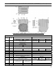
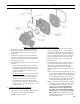
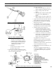
Figure 5: Boiler Tapping Locations and Usage (Knockdown Boilers Only)
PURPOSE OF TAPPINGS
Tapping
Location
Size
NPT
Steam Boiler Water Boiler
Non-Heater w/Heater Non-Heater
Front Heater
Rear Heater
A ¾"
Pressure Limit (Probe LWCO)
Plugged (Float LWCO)
L7248
Boiler Control
L7224
Boiler Control
Flush Plug
B ¼" Pressure Gauge Temperature/Pressure Gauge
C ¾"
Probe LWCO Std.
Plugged (Float LWCO)
N/A
C-C ¾" Flush Plug Flush Plug N/A
D ½"
Water Gauge Glass (Probe LWCO)
Water Gauge Glass, Pressuretrol, and LWCO (Float)
N/A
F ¾" N/A L4006A Operating Control N/A N/A
L7224
Boiler Control
G 1½" Bushed to ¾" for Drain Valve (Optional Return) Return
H 1½" Return Plugged
J 1½" Surface Blowoff - Plugged Flush Plug
K 2" Front Supply (3 thru 9 Section) Front Supply (3 thru 9 Section)
L 2"
Plugged, Optional Second Supply (3 thru 5 Section)
Required Second Supply (6 thru 9 Section)
Plugged (3 thru 9 Section)
M ¾" Safety Valve Relief Valve
P ¾" Auxiliary Tapping - Plugged
Aux. Tapping -
Plugged
N/A
Aux. Tapping -
Plugged
R ¾"
Aux. Tapping - Plugged
(Indirect Return)
Aux. Tapping - Plugged
(Indirect Return)
*
Auxiliary Tapping - Plugged
S ½" Indirect Limit
Indirect Limit
*
N/A
T 1" Indirect Supply
Indirect Supply
*
N/A
* In lieu of Tankless Heater
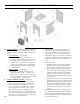
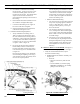
SECTION III: KNOCKDOWN BOILER ASSEMBLY (continued)