
Install Instructions

16
NOTICE
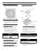
When securing burner swing door make sure door
is drawn-in equally on both sides.
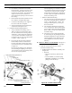
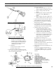
Step 3. Use a hand wrench to tighten door hardware
and always start with the right side ange
nut rst (see Figure 13B). Use an alternating
tightening method from right side ange nut
to left side ange bolt to tighten door equally
until sealed without applying excessive torque.
Never tighten left side ange bolt rst or tighten
either piece of hardware 100% without using the
alternating tightening method described above.
Failure to follow the prescribed procedure could
cause thread damage to casting or a leak in the
door seal. If left side ange bolt is tightened
before right side ange nut, right side of door
can not be drawn-in to provide an air tight seal,
as shown in Figure 13C. Applying excessive
torque will only cause thread damage.
5. Place oil burner gasket on burner and align holes.
CAUTION
DO NOT install burner without gasket.
6. Back out (4) 5/16”-18 x 3/4” long cap screws
factory installed into burner swing door about 1/4".
Insert oil burner into the opening of the burner door,
rotate slightly clockwise to align burner mounting
ange teardrop cutouts with cap screw hex heads
and engage all four cap screws simultaneously.
Then, rotate the burner slightly counterclockwise,
level it and fully tighten all four cap screws.
7. Inspect electrodes, head setting and factory installed
oil nozzle.
NOTICE
The burner for knockdown boilers has a pre-
installed nozzle for steam applications. For water
boiler applications, refer to Paragraph 8 in this
Section for installation instructions to change
nozzles.
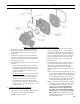
a. Remove burner cover.
b. Loosen two (2) igniter latching screws, rotate
tabs and swing open igniter about hinge.
c. Loosen knurled nut and disconnect copper
connector tube.
d. Remove nozzle line electrode assembly.
e. Remove Beckett MD(V1) or MB(L1) Head.
f. Inspect and measure burner electrodes. Refer
to Figure 29A for the proper electrode setting.
Readjust electrode setting to the proper
dimensions if necessary.
g. Reinstall Beckett MD(V1) or MB(L1) Head.
h. Reinstall nozzle line electrode assembly.
i. Connect copper connector tube.
j. Inspect Beckett head setting on left side of
burner by insuring the blue line MD(V1) or the
line on the label MB(L1) are aligned, readjust if
necessary.
k. Tighten knurled nut.
l. Swing igniter closed, rotate tabs and tighten two
(2) igniter screws.
m. Replace burner cover and tighten burner cover
knobs.
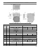
8. For water boiler applications, refer to Table 12 at
the rear of this manual for proper nozzle and burner
settings.
a. Remove nozzle for water application attached to
copper connector tube.
b. Loosen two (2) igniter latching screws, rotate
tabs and swing open igniter about hinge.
c. Loosen knurled nut and disconnect copper
connector tube.
d. For V8H3, remove the Low re Bafe.
e. Remove nozzle line electrode assembly.
f. Remove Beckett MD(V1) or MB(L1) Head.
g Remove nozzle for steam application from
nozzle adapter and install the water application
nozzle provided in Step 8a above. Refer to
Burner Specications, Table 12 at the rear of this
manual for proper nozzle and burner settings.
The nozzle must be securely installed to assure
leak free joints between the nozzle and adapter.
When installing the nozzle, be careful not to
bump or move the burner electrodes.
h. Inspect and measure burner electrodes. Refer
to Figure 29A for the proper electrode setting.
Readjust electrode setting to the proper
dimensions if necessary.
i. Reinstall Beckett MD(V1) or MB(L1) Head.
j. Reinstall nozzle line electrode assembly.
k. Connect copper connector tube.
l. Inspect Beckett head setting on left side of
burner by insuring the blue line MD(V1) or the
line on the label MB(L1) are aligned, readjust if
necessary.
m. Tighten knurled nut. Connect the ared tting
on the copper oil line to the nozzle line and
tighten.
n. Swing igniter closed, rotate tabs and tighten two
(2) igniter screws.
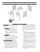
K. INSTALL CARLIN ELITE EZ OIL BURNER,
3 thru 6 Section (See Figure 7).
Follow instructions in Paragraph J, Steps 1 through 6.
SECTION III: KNOCKDOWN BOILER ASSEMBLY (continued)