
Install Instructions

18
iii. Re-install the combustion head assembly
into the air tube. It may be necessary to turn
nozzle line assembly upside down to ease
insertion into the air tube. Then the threaded
adapter on the end of the nozzle line is
passed through the opening in the left side of
the housing.
iv. Run the aluminum (knurled) thumb-nut onto
the nozzle line and tighten hand-tight.
v. Connect the ared tting on the copper oil
line to the nozzle line and tighten.
vi. Swing the transformer to the closed position,
rotate latches and tighten screws.
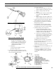
b. Combustion Head Setting/Adjustment
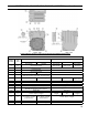
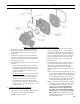
i. Verify combustion head setting, refer to
Table 12 at the rear of this manual. Read
the scale embossed in the housing, which is
calibrated in 1/16-inch divisions (dimension
‘A’) the position of the ame retention ring
in relation to the air cone can be determined
at a glance. Refer to Figure 7A.
ii. By moving the electrode and combustion
head assembly forward or backward, the
location of the ame retention ring relative
to the throttle ring can be controlled. Refer
to Figure 7A.
By loosening the locking screw and thumb-
nut and turning the adjusting screw using a
5/32-inch allen wrench, the assembly can be
moved to the required position.
Turn the adjusting crew clockwise to move
the combustion head forward, increasing the
‘A’ dimension, counterclockwise will pull
the head back, decreasing the ‘A dimension.
To lock in place, rst tighten the thumb-nut
and then the locking screw.
c. Initial Air Shutter/Band Setting
i. The air shutter has a pointer which indicated
the percent of opening against a calibrated
scale (9 = 90%, fully open = 100%). The
setting is locked in place by a screw just
above the fuel unit.
ii. The air band is adjusted by loosening the
screw, rotating the air band and then tighten
screw to lock in place after nal adjustment.
Refer to Table 12 at the rear of this manual
for initial settings.
iii. The burner is now set at the approximate
air band setting for the gallonage indicated.
During nal adjustment, using combustion
testing equipment, the air band may need
minor adjustment to achieve the desired
efciency.
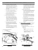
M. INSTALL RIELLO OIL BURNER. (See Figure 7).
Follow instructions in Paragraph J, Steps 1 through 6.
7. Verify oil nozzle installed in burner, inspect
electrodes and head setting.
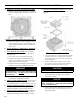
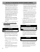
a. Installation/Removal of Drawer assembly, refer
to Figure 7B.
i. Removal:
• Disconnect oil delivery tube nut from
pump.
• Loosen SCREW (3), and then unplug
PRIMARY CONTROL (1) by carefully
pulling it back and then up.
Figure 7B: Installation/Removal of
Riello Drawer Assembly
SECTION III: KNOCKDOWN BOILER ASSEMBLY (continued)
Figure 7A: Combustion Head Adjustment -
102CRD Burner