
Install Instructions

19
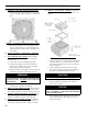
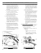
If nozzle needs replacement, follow steps below
Also refer to Figure 7C.
i. Remove the nozzle adapter (2) from the
drawer assembly by loosening the screw (1).
ii. Remove existing nozzle from nozzle
adapter.
iii. Insert the proper nozzle into nozzle adapter
and tighten securely (DO NOT over
tighten).
iv. Replace adapter, with nozzle installed, into
drawer assembly and secure with screw (1).
c. Inspect and measure burner electrodes. Refer to
Figure 29D for the proper electrode settings.
d. Re-install Drawer Assembly into Combustion
Head per Step 7a above.
e. Insertion Depth, verify the distance between
the tip of the end cone is equal to the distance
specied in Table 12 at the rear of this manual.
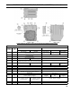
f. Turbulator Setting, refer to Figure 7D.
i. Conrm the turbulator setting is correct
for input oil nozzle installed in the burner,
readjust, if needed, to index mark specied
in Table 12 at the rear of this manual.
ii. Loosen nut (1) and turn screw (2) until the
index marker (3) is aligned with the correct
index number in the Burner Setup Chart
(Table 12 at the rear of this manual).
iii. Retighten the retaining nut (1).
MODEL F5 (3 thru 5 Section): Zero and four
are scale indicators only. From left to right the
rst line is 4 and the last line 0.
MODEL F10 (6 thru 9 Section): Same as above,
except, scale indicators are 0 and 5.
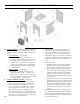
g.. Pump Connections and Port Identication, refer
to Figure 7E.
This burner is shipped with the oil pump set
to operate on a single line system. To operate
on a two-line system the bypass plug must be
installed.
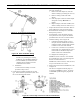
Figure 7C: Riello Nozzle Replacement
Figure 7D: Riello Turbulator Setting
Figure 7E: Riello Pump Connections and Port Identication
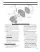
• Remove the AIR TUBE COVER
PLATE (5) by loosening the retaining
SCREW (4) (Two SCREWS-Model F5).
• Loosen SCREW (2), and then slide the
complete drawer assembly out of the
combustion head as shown.
ii. Installation:
To insert drawer assembly, reverse the
procedure in Step i above.
b. Check factory installed oil nozzle for size and
type. Refer to Burner Specications, Table 12 at
the rear of this manual for details.
SECTION III: KNOCKDOWN BOILER ASSEMBLY (continued)