
Install Instructions

20
WARNING: DO NOT operate a single line system
with the by-pass plug installed. Operating a
single line system with the by-pass plug installed
will result in damage to the pump shaft seal.
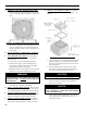
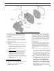
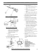
NOTE: Pump pressure was factory pre-set but
must be checked at time of burner start-up. A
pressure gauge is attached to the PRESSURE/
BLEEDER PORT (7) for pressure readings. Two
PIPE CONNECTORS (4) are supplied with the
burner for connection to either a single or two-
line system. Also supplied are two ADAPTORS
(3), two female ¼” NPT to adapt oil lines to
burner pipe connectors. All pump port threads
are British Parallel Thread design. Direct
connection of NPT threads to the pump will
damage the pump body.
Riello manometers and vacuum gauges DO
NOT require any adapters, and can be safely
connected to the pump ports. An NPT x metric
adapter must be used when connecting other
gauge models.
g. Replace Burner Cover and Tighten Burner Cover
Screws.
N. INSTALL TRIM AND CONTROLS WITH
BECKETT BURNER. - Water Boilers Only
(See
Figures 1A, 1B, 1C and 5).
1. Thread combination pressure/temperature gauge into
¼” NPT tapping. Tighten with wrench applied to the
square shank of the gauge.
CAUTION
DO NOT apply pressure to the gauge case - this
may result in inaccurate readings.
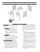
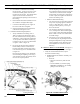
2. Lower front section tapping “G” is used for standard
return on water boilers, see Figure 5. If circulator
(supplied with boiler) is to be mounted in return
piping connected directly to 1½" NPT boiler return
tapping "G", use the piping arrangements outlined
in steps a. thru e. as follows: (see Figures 15A and
15B)
a. Thread 1½” NPT x 3” long nipple and 1½”
NPT x 90° elbow with ¾" NPT side outlet
into the return tapping and tighten with a pipe
wrench.
b. Screw drain valve into ¾" NPT side outlet of the
1½” NPT x 90° elbow.
c. Thread 1½” NPT x 18” long nipple (supplied
by others) into the 1½" NPT x 90° elbow and
tighten with a pipe wrench.
d. Thread one of the circulator ange onto the
nipple and tighten with a pipe wrench. Position
ange so that the bolt slots are parallel to the
boiler front.
e. Place a circular ange gasket in the ange
groove on the circulator and mount the circulator
on the ange. Note that this is the return piping
and the ow arrow on the circulator should point
down . Fasten circulator with 7/16” - 14 x 1½"
long cap screws and 7/16" - 14 nuts.
f. Fasten the second circulator ange and gasket to
the circulator.
g. Remove supplied circulator harness from Part
Bag. Remove circulator junction box cover and
knockout in circulator junction box ange. Insert
harness end with two wires having bare-stripped
ends through knockout hole and push-in to
engage harness connector into ange. Connect
harness conductors to circulator junction box
wires as follows - White to White and Blue to
Yellow (or, Blue) and secure with wire nuts
(installer provided).
3. Install relief valve, as shown in Figure 1A, 1B, and
1C, onto ¾” NPT x 8” nipple previously installed in
Paragraph H, No. 2, step b. Tighten with wrench.
Pipe discharge as shown in Figures 15A and 15B.
Installation of the relief valve must be consistent
with ANSI/ASME Boiler and Pressure Vessel Code,
Section IV.
WARNING
Safety valve discharge piping must be piped near
oor to eliminate potential of severe burns. DO
NOT pipe in any area where freezing could occur.
DO NOT install any shut-off valves, plugs or caps.
4. On boilers without a heater opening, install the well
into the 3/4” NPT tapping “A” located on the front
of the boiler in the upper left corner. See Figures 1A
and 5. Tighten the well and fully insert limit sensor
into immersion well such that the tip on the limit
sensor touches the bottom of the immersion well.
See Figure 8. Secure control to immersion well with
setscrew.
WARNING
Aquastat bulb must be fully inserted into the
well.
5. On boilers with a heater opening, install the well
in either the 1/2” NPT or 3/4” NPT tapping on the
tankless heater plate or cover plate. See Figures
1B, 1C and 5. Tighten the well and fully insert
limit sensor into immersion well such that the tip
on the limit sensor probe touches the bottom of the
immersion well. See Figure 8. Secure control to
immersion well with setscrew.
SECTION III: KNOCKDOWN BOILER ASSEMBLY (continued)