
Install Instructions


24
SECTION IV: PACKAGED BOILER ASSEMBLY
A. REMOVE CRATE.
1. Remove all fasteners at crate skid.
2. Lift outside container and remove all other inside
protective spacers and bracing. Remove draft
regulator box and miscellaneous trim bag containing
safety or relief valve, and pipe ttings.
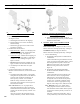
B. REMOVE BOILER FROM SKID.
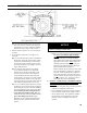
1. Boiler is secured to base with 4 bolts, 2 in front and
2 in rear of shipping skid, see Figure 12. Remove all
bolts.
2. Tilt boiler to right and to rear. Using right rear leg
as pivot, rotate boiler 90° in a clockwise direction,
and lower left side of boiler to oor. Tilt boiler and
remove crate skid. Care should be exercised to
prevent damage to jacket or burner.
Figure 12 : Packaged Boiler Removal from Skid
CAUTION
DO NOT drop boiler. DO NOT bump boiler jacket
against oor.
C. MOVE BOILER TO PERMANENT POSITION
by sliding or walking.
D. PROCEDURE TO OPEN, CLOSE AND SECURE
BURNER SWING DOOR with articulated hinge.
Throughout this manual you will be instructed to
open and close the burner swing door for various
reasons. There is a proper and improper method to
closing and securing the burner swing door after it
has been removed and re-installed for Field Assembly
(Knockdown Boiler) or opened for inspection, cleaning
or eld service.
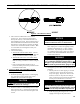
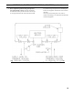
1. TO OPEN BURNER SWING DOOR (see Figures
13A and 13B).
Step 1. Loosen and remove right side latching
hardware (5/16" ange nut and washer).
Step 2. Loosen and remove left side hinge hardware
(5/16" x 3-1/2" lg. hex head ange bolt).
Step 3. The duel pivot articulated hinge allows right
side of door to be pulled outward and rotated
to the left all in one motion. To do so, place
your right hand under burner air tube and lift up
slightly to help carry the weight of the door and
burner. Use your left hand to grasp the door's
left side hinge ange, pull outward to rotate the
hinge, this motion will move the door outward
and to the left approximately 3" (see Figure 13B,
Position 2).
SECTION III: KNOCKDOWN BOILER ASSEMBLY (continued)
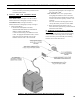
If you are using a burner with the disconnect harness,
complete the following assembly instructions for
mounting the mating burner disconnect junction box,
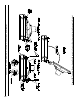
see Figure 11.
1. Remove (2) #6 x 1/2" lg. machine screws and J-box
cover from junction box.
2. Secure 2" x 4" junction box to jacket front panel
with (2) #8 x 3/8" lg. sheet metal screws using pre-
punched holes below tridicator or pressure gauge
tapping.
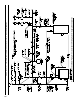
3. Complete the eld wiring phase of Paragraphs N &
O (Beckett), P (Carlin) or Q (Riello) Install end of
harness from low water cut-off (LWCO), R8239A
Control Center or Boiler Control into appropriate
knockout of burner disconnect junction box
according to source, refer to Figures 1A thru 1D.
4. Connect (3) wires from boiler control LWCO or
R8239A Control Center to spade terminals on rear
of power outlet receptacle. Make the connections
as shown in appropriate wiring diagram based on
boiler conguration, refer to Figures 21A thru 25.
5. Secure J-box cover to junction box with (2) #6 x ½"
lg. machine screws.
6. Insert mating end of burner disconnect harness
(power cord) into power outlet receptacle on J-box.