
Install Instructions


34
SECTION VII: TANKLESS AND INDIRECT WATER HEATER PIPING
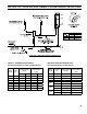
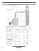
A. CONNECT TANKLESS HEATER PIPING as
shown in Figure 17A. See Tables 2A and 2B for
Tankless Heater Rating.
WARNING
Install automatic mixing valve at tankless heater
outlet to avoid risk of burns or scalding due to
excessively hot water at xtures. Adjust and
maintain the mixing valve in accordance with the
manufacturer's instructions. DO NOT operate
tankless heater without mixing valve.
THE FOLLOWING GUIDELINES SHOULD BE
FOLLOWED WHEN PIPING THE TANKLESS
HEATER:
1. FLOW REGULATION — If ow through the
heater is greater than its rating, the supply of
adequate hot water may not be able to keep up
with the demand. For this reason a ow regulator
matching the heater rating should be installed in
the cold water line to the heater. The ow regulator
should preferably be located below the inlet to the
heater and a minimum of 3’ away from the inlet
so that the regulator is not subjected to excess
temperatures that may occur during “off” periods
when it is possible for heat to be conducted back
through the supply line. The ow regulator also
limits the ow of supply water regardless of inlet
pressure variations in the range of 20 to 125 psi.
2. TEMPERING OF HOT WATER — Installation
of an automatic mixing valve will lengthen the
delivery of the available hot water by mixing some
cold water with the hot. This prevents the possibility
of scalding hot water at the xtures. In addition,
savings of hot water will be achieved since the user
will not waste as much hot water while seeking a
water temperature. Higher temperature hot water
required by dishwashers and automatic washers is
possible by piping the hot water from the heater
prior to entering the mixing valve. The mixing valve
should be “trapped” by installing it below the cold
water inlet to heater to prevent lime formation in the
valve. Refer to Figure 17A.
3. FLUSHING OF HEATER — All water contains
some sediment which settles on the inside of the
coil. Consequently, the heater should be periodically
back washed. This is accomplished by installing
hose bibs as illustrated and allowing water at city
pressure to run into hose bib A, through the heater,
and out hose bib B until the discharge is clear. The
tees in which the hose bibs are located should be
the same size as heater connections to minimize
pressure drop.
4. HARD WATER — A water analysis is necessary
to determine the hardness of your potable
water. This is applicable to some city water and
particularly to well water. An appropriate water
softener should be installed based on the analysis
and dealer’s recommendation. This is not only
benecial to the tankless heater but to piping and
xtures plus the many other benets derived from
soft water.
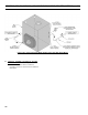
NOTICE
During summertime operation, the normal
water line on a steam boiler can be raised
1", from 22-5/8" to 23-5/8" (see Figure 1D) for
improved tankless heater performance on
steam boilers.
Use street elbow ttings in tankless in and out
connections to assure adequate clearance of
piping.
CAUTION
Use of hard water with a tankless coil will, over a short period of time, reduce the output of the coil, reduce
ow due to increased pressure drop and reduce the useful life of the coil.