
Install Instructions


39
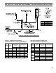
2. After determining location, cut a hole in the wall to
accept 4 inch air intake pipe. See Figure 20.
3. Remove the metal knockout in right side of burner
cover. Install U.S. Boiler Company Inlet Air
Accessory Kit, P/N 611280031.
4. Mount the Vacuum Relief Valve Tee Assembly (P/N
8116268 included with Kit) or 90° elbow into the
burner inlet ring. See Figure 20.
a. Secure with at least three (3) sheet metal screws
evenly spaced around the burner inlet ring.
b. Assembly the vacuum relief valve balance
weight onto the gate. Refer to the vacuum relief
valve manufacturer's instructions.
c. Mount the vacuum relief valve into the tee and
fasten with a screw and nut in collar tabs. To
ensure proper operation, the gate must be level
across the pivot point and plumb. Refer to
vacuum relief valve manufacturer's instructions.
5. Install remainder of air intake, securing each joint
with at least three (3) sheet metal screws evenly
spaced.
6. Install air intake terminal. See Figure 20.
NOTICE
Intake terminal must be at least 12 inches above
grade plus snow accumulation.
7. Seal all external joints with weatherproof caulk.
WARNING
DO NOT locate air intake where petroleum
distillates, CFC's, detergents, volatile vapors or
any other chemicals are present. Severe boiler
corrosion and failure will result.
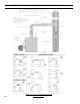
Figure 20: Optional Air Intake Piping Installation - Only Available with Beckett Burner
SECTION VIII: VENTING AND AIR INTAKE PIPING (continued)