
Install Instructions

53
prepurge the motor and igniter will operate but the
oil valve will remain closed. Refer to Oil Primary
Control Instructions for more details.
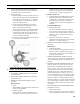
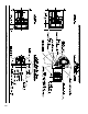
4. Adjust oil pressure.
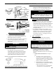
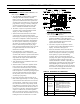
a. When checking a fuel unit's operating pressure, a
reliable pressure gauge may be installed in either
the bleeder port or the nozzle port. For Beckett
and Carlin burners refer to Figure 28. Refer to
Figure 7E for Riello burner.
b. Locate oil pressure adjusting screw and turn
screw to obtain proper pump pressure, refer to
Table 12 at the rear of this manual.
c. To check the cutoff pressure, deadhead a reliable
pressure gauge onto the copper connector tube
attached to the nozzle port. Run the burner for
a short period of time. Shut the burner off. The
pressure should drop and hold.
d. Remove the gauge and install bleeder port and/or
reconnect the nozzle port line.
SECTION XI: SYSTEM START-UP (continued)
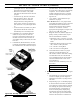
Figure 28: Adjusting Fuel Pump Pressure
G. ADJUST OIL BURNER WHILE OPERATING.
(ame present)
1. SET ROOM THERMOSTAT about 10°F below
room temperature.
2. PRESS RED RESET BUTTON on Oil Primary
Control and release.
3. READJUST THE HEAD SETTING only if
necessary.
Beckett Burners
a. V8H3:
Beckett MB(L1) Head burners have a xed head
which are non-adjustable.
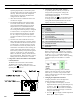
b. V8H4 thru V8H9:
Beckett MD(V1) (variable) Head burners have
the ability to control air by moving the head. It
might be necessary to move the head forward
or back one position at a time to optimize the
smoke and CO
2
readings. See Figure 29A.
Carlin Elite EZ Burners
a. Carlin EZ-1HP and EZ-2HP burners use a head
positioning bar to x the head setting based
on nozzle size. To adjust this setting, bar must
be changed to the next larger or smaller bar
available. Refer to Section III, Paragraph K, 7b
for details.
Carlin 102CRD Burners
a. V8H7 through V8H9
The Carlin 102 CRD-3 Burner has the ability
to control air by moving the head. It might be
necessary to move the head forward or back one
position at a time to optimize the smoke and
CO2 readings.
b. If the re is a little too rich, move the
combustion head slightly forward by increasing
dimension “A”. Refer to Figure 7A.
4. READJUST THE TURBULATOR SETTING only
if necessary.
Riello Burners
a. V8H3 through V8H9
Move the turbulator setting forward or back one
position at a time to optimize the smoke and
CO2 readings. Refer to Figure 7D and Table 12
at the rear of this manual.
5. ADJUST DRAFT REGULATOR for a draft of
-0.02" (water gauge) over the re after chimney has
reached operating temperature and while burner is
running.
6. READJUST THE AIR DAMPER SETTING (Air
Band, Air Shutter or Air Gate) on the burner for
a light orange colored ame while the draft over
the re is -0.02”. Use a smoke tester and adjust
air for minimum smoke (not to exceed #1) with a
minimum of excess air. Make nal check using
suitable instrumentation to obtain a CO
2
of 11.5
to 12.5% with draft of -0.02” (water gauge) in re
box. These settings will assure a safe and efcient
operating condition. If the ame appears stringy
instead of a solid re, try another nozzle of the same
type. Flame should be solid and compact. After all
adjustments are made recheck for a draft of -0.02”
over the re.
7. ONLY READJUST THE HEAD/TURBULATOR
SETTING if necessary.
a. V8H3 through V8H9
Move the setting forward or back one position at
a time to optimize the smoke and CO
2
readings.