
Install Instructions

55
8. Steps outlined in Paragraph 5 and 6 above must
be repeated every time the Head/Turbulator or Air
Band/ Damper Setting is readjusted.
9. Turn “OFF” burner and remove Riello Combination
Pressure Gauge and Bleeder Valve Assembly.
Install pressure port/bleeder plug and tighten. Start
burner again.
WARNING
DO NOT loosen or remove any oil line ttings
while burner is operating.
10. FLAME FAILURE
The V8H boiler controls operate the burner
automatically. If for unknown reasons the burner
ceases to re and the reset button on the primary
control has tripped, the burner has experienced
ignition failure. Refer to Oil Primary Control
features, Paragraph I, Step 2 of this Section and
Section XV, Troubleshooting, Paragraph B. If
the failure re-occurs, call your heating contractor
immediately before pressing the reset button.
WARNING
DO NOT attempt to start the burner when excess
oil has accumulated, when the boiler is full of
vapor, or when the combustion chamber is very
hot.
H. CHECK FOR CLEAN CUT OFF OF
BURNER.
1. AIR IN THE OIL LINE between fuel unit and
nozzle will compress when burner is on and will
expand when burner stops, causing oil to squirt from
nozzle at low pressure as burner slows down and
causing nozzle to drip after burner stops. Usually
cycling the burner operation about 5 to 10 times will
rid oil line of this air.
2. IF NOZZLE CONTINUES TO DRIP, repeat
Paragraph H, No. 1 above. If this does not stop the
dripping, remove cut-off valve and seat, and wipe
both with a clean cloth until clean, then replace
and readjust oil pressure. If dripping or after burn
persist replace fuel pump.
I. TEST CONTROLS.
1. Check thermostat operation. Raise and lower
thermostat setting as required to start and stop
burner.
WARNING
Before installation of the boiler is considered
complete, the operation of all boiler controls must
be checked, particularly the primary control and
high limit control.
2. VERIFY OIL PRIMARY CONTROL
FEATURES using procedures outlined in
Instructions furnished with control or instructions as
follows:
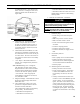
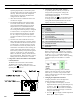
a. GeniSys 7505 Control Features, see Figure
30A.
i. The GeniSys 7505 is a microprocessor-
based control. The indicator light provides
diagnostic information for lockout, recycling
and cad cell status. There is a manual reset
button to exit the Lockout Mode.
ii. Pump Priming Cycle: To facilitate purging
air from the oil lines and lters, the 7505 can
be placed in a purge routine by:
• After the burner starts, press and hold the
reset button for 15 seconds until the
SECTION XI: SYSTEM START-UP (continued)
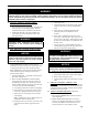
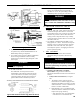
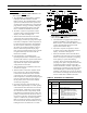
Figure 29B: Electrode Positioning, Retention Ring
Assembly and Nozzle Adapter (Carlin EZ-1 / EZ-2)
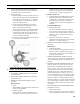
Figure 29C: Combustion Head / Nozzle /
Electrode Settings (Carlin 102CRD)
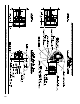
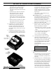
Figure 29D: Electrode Positioning (Riello 40 Series)