
Install Instructions

56
yellow light turns on. This indicates that
the button has been held long enough.
• Release the reset button. The yellow
light will turn off and the burner will start
up again.
• At burner start up, click the reset button
while the igniter is till on. This will
transition the control to a dedicated
Pump Prime mode, during which the
motor, igniter, and valve are powered for
four (4) minutes. The yellow light will be
on.
• At the end of four (4) minutes, the yellow
light will turn off and the control will
automatically return to standby mode.
iii. Limited Recycle: This feature limits the
number of recycle trials (for each call
for heat) to a maximum of three trials. If
the ame is lost three times and does not
successfully satisfy a call for heat, the 7505
locks out.
iv. Limited Reset (Restricted Mode): In order
to limit the accumulation of unburned oil in
the combustion area, the control can only be
SECTION XI: SYSTEM START-UP (continued)
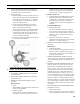
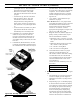
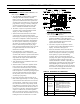
Figure 30A: GeniSys 7505 Oil Primary Terminals,
LED's and Reset Button
reset three times. The reset count returns to
zero each time a call for heat is successfully
completed. To reset a Restricted Mode
lockout, hold button down for 15 seconds
until the red light turns off and the yellow
light turns on.
v. "T-T" Jumper: Select models have pre-
installed "T-T" jumper.
Note: DO NOT remove "T-T" jumper unless
wiring diagram indicates a direct connection
from thermostat and/or tankless heater
aquastat control to the oil burner primary
control's "T-T" terminals. Refer to
appropriate wiring diagram, see Figure 21A,
21B, 22, 23A, 23B, 24A or 24B.
vi. Diagnostic LED: The indicator light on oil
primary control provides lockout, recycle
and cad cell indications as follows:
• Flashing at 1 Hz (½ second on, ½ second
off): system is locked out or in Restricted
Mode.
• Flashing at ¼ Hz (2 seconds on, 2 seconds
off): control is in Recycle Mode.
• On: cad cell is sensing ame.
• Off: cad cell is not sensing ame.
vii. Cad Cell Resistance Check: For proper
operation it is important that the cad
cell resistance is below 1600 ohms. During
a normal call for heat, the cad cell leads
can be unplugged from the control and the
resistance measured with a meter in the
conventional way.
Conduct these tests with ame present, see
chart below.
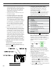
Flame Detection Range
Normal (0 - 1600 ohms)
Limited (1600 ohms to lockout)
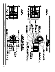
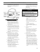
b. Honeywell R7284 Control Features, see Figure
30B.
i. The Oil Primary is a microprocessor-based
control. The display provides diagnostic
information for lockout, recycling and cad
cell status.
ii. Pump Priming Cycle: To facilitate purging
air from the oil lines and lters, the R7284
can be placed in a purge routine by pressing
and releasing the up arrow button during
the Trial For Ignition. “Pump Prime” is
shown on the oil primary display along
with the time left on the Trail for Ignition
(TFI). Pressing the up arrow button adds a
minute to the TFI time for a maximum of