
Install Instructions

72
B. OIL PRIMARY CONTROL (Oil Primary)
1. Burner (Oil Primary) will not come on.
a. No power to Oil Primary.
b. Oil Primary is in lockout or restricted mode.
Press reset button for one (1) second to exit
lockout. If control has recycled three times
within the same call for heat, it will enter into
restricted mode. To reset from restricted mode,
refer to Section XI, Paragraph I, No. 2 for
details.
c. CAD cell seeing light.
d. CAD assembly defective.
e. Control motor relay is stuck closed (see note
below).
2. Burner (control) will light, then shut down after a
short time, then restart after one (1) minute.
a. CAD cell is defective.
b. Air leaking into oil line causing ame out.
c. Defective nozzle causing ame to be erratic.
d. Excessive airow or draft causing ame to leave
burner head.
e. Excessive back pressure causing ame to be
erratic.
3. Control locks out after Trial For Ignition (TFI).
a. No oil to burner.
b. Shorted electrodes.
c. Nozzle clogged.
d. Airow too high.
e. Ignitor module defective.
f. CAD cell defective.
g. Oil valve stuck open or closed.
Note: The Safety Monitoring Circuit (SMC) is
designed to provide lockout in the event of a
stuck or welded motor relay.
NOTICE
If ame is not established within 15 seconds of
oil valve actuation (known as Trial For Ignition
[TFI]) lockout will occur. Lockout is indicated
by a red LED solid-on located on the oil primary
control.
Hard Lockout will occur if the Oil Primary
Control locks-out three (3) times during a call
for heat. This is indicated by red light reset
button solid-on.
C. INTELLIGENT OIL BOILER CONTROL
• Cold Start Boiler Control is used on Boilers without
Tankless Heaters.
• Warm Start Boiler Control is used on Boilers with
Tankless Heaters
1. When a problem occurs with the boiler operation,
the Boiler Control easily provides specic, valuable
information to help resolve the issue quickly. The
display on the Boiler Control should be the rst
place to check.
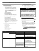
a. If an Error Code "Err" IS NOT displayed on the
Boiler Control: In this circumstance,
Table 10 can be used to determine the problem
and possible causes.
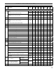
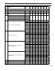
System Condition Diagnostic Condition Check Action
Boiler is cold, house is
cold.
Display is OFF. 120 Vac System power. Turn system power on.
Display is ON. 24 Vac T-T No 24 V; replace control.
24 V present; disconnect
thermostat, short T-T.
Boiler starts, check wiring and thermostat.
120 Vac at B1-B2 • If no, replace control.
• If yes, check burner and wiring.
Refer to Err on display. -----
Boiler is hot, house is
cold.
Display is ON. 120 Vac at C1-C2 • 120 Vac at C1-C2, check wiring
to pump.
• Wiring OK, is pump running?
• If not, replace the pump.
• If pump is running, check for
trapped air or closed zone valves
Boiler below the Low Limit
temperature, wait for boiler to go
above Low Limit temperature.
-----
Boiler above LL? If yes, check
for 120 Vac between ZC and L2.
• If no 120 Vac , replace control.
• If yes, check zone relays, circulators
and wiring.
TABLE 10: TROUBLESHOOTING GUIDE
SECTION XV: TROUBLESHOOTING (continued)