INSTALLATION, OPERATING AND SERVICE INSTRUCTIONS FOR PVG™ Gas - Fired Boiler 9700609 As an ENERGY STAR® Partner, U.S. Boiler Company has determined that the PVG Series meets the ENERGY STAR® guidelines for energy efficiency established by the United States Environmental Protection Agency (EPA). For service or repairs to boiler, call your heating contractor. When seeking information on boiler, provide Boiler Model Number and Serial Number as shown on Rating Label.
IMPORTANT INFORMATION - READ CAREFULLY NOTE: The equipment shall be installed in accordance with those installation regulations enforced in the area where the installation is to be made. These regulations shall be carefully followed in all cases. Authorities having jurisdiction shall be consulted before installations are made. All wiring on boilers installed in the USA shall be made in accordance with the National Electrical Code and/or local regulations.
Special Installation Requirements for Massachusetts A. For all side wall horizontally vented gas fueled equipment installed in every dwelling, building or structure used in whole or in part for residential purposes and where the side wall exhaust vent termination is less than seven (7) feet above grade, the following requirements shall be satisfied: 1.
WARNING This boiler requires regular maintenance and service to operate safely. Follow the instructions contained in this manual. Improper installation, adjustment, alteration, service or maintenance can cause property damage, personal injury or loss of life. Read and understand the entire manual before attempting installation, start-up operation, or service. Installation and service must be performed only by an experienced, skilled, and knowledgeable installer or service agency.
Table of Contents I. Pre-Installation................................ 7 VIII. System Start-up............................. 37 II. Unpack Boiler................................. 8 IX. Operation...................................... 41 III. Venting............................................ 9 X. Troubleshooting............................ 45 IV. Water Piping and Trim.................. 21 XI. Service........................................... 50 V. Gas Piping.....................................
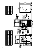
Supply 1¼ NPT 1¼ NPT 1¼ NPT 1¼ NPT 1¼ NPT 1¼ NPT 1¼ NPT Model PVG3A PVG4A PVG5A PVG6A PVG7A PVG8A PVG9A 1¼ NPT 1¼ NPT 1¼ NPT 1¼ NPT 1¼ NPT 1¼ NPT 1¼ NPT Return 3 3 3 3 3 4 4 Vent ¾ NPT ¾ NPT ¾ NPT ¾ NPT ¾ NPT ¾ NPT ¾ NPT Relief Valve PVG CONNECTION SIZES(DIMENSIONS IN INCHES) Figure 2: Dimensions PVG3A PVG4A PVG5A PVG6A PVG7A PVG8A PVG9A Model 11.65 14.72 17.78 20.84 23.90 26.97 30.
I. Pre-Installation WARNING F. Provide combustion and ventilation air in accordance If you do not follow these instructions exactly, a fire or explosion may result causing property damage or personal injury. with applicable provisions of local building codes, or: USA - National Fuel Gas Code, NFPA 54/ANSI Z223.1, Air for Combustion and Ventilation; Canada - Natural Gas or Propane Installation Code, CAN/CSA-B149.1.
I. Pre-Installation (continued) by duct with the outdoors or spaces (crawl or attic) freely communicating with the outdoors. Locate one opening within twelve (12) inches of top of space. Locate remaining opening within twelve (12) inches of bottom of space. Minimum dimension of air opening is three (3) inches. Size each opening per following: space(s) of sufficient volume such that combined volume of all spaces meet criteria for unconfined space.
III. Venting WARNING Do not use this boiler with galvanized, Type 304 or Type 316 stainless steel, non metallic or any other non AL29-4C® based vent systems. Do not use a barometric damper or draft hood with this appliance. Do not use vent dampers with this boiler. Moisture and ice may form on surfaces around termination. To prevent deterioration, surfaces should be in good repair (sealed, painted, etc.).
III. Venting (continued) Table 3: Vent System Components Vent System Component Equivalent Feet of Pipe Part Number 3” Dia. Pipe x 1 Ft 8116296U 4” Dia. Pipe x 1 Ft 100176-01 3” Dia. Pipe x 3 Ft 8116298U 4” Dia. Pipe x 3 Ft 100177-01 3” Dia. Pipe x 5 Ft 8116300U 4” Dia. Pipe x 5 Ft 100178-01 3” Dia. Pipe x Adjustable 8116319U 4” Dia. Pipe x Adjustable 100179-01 3” Dia. 90° Elbow 8116294U 4” Dia. 90° Elbow 100180-01 3” Dia. 45° Elbow 8116292U 4” Dia. 45° Elbow 100181-01 3” Dia.
III. Venting (continued) A. Vent Guidelines Due to Removal of an Existing Boiler For installations not involving the replacement of an existing boiler, proceed to Step B. When an existing boiler is removed from a common venting system, the common venting system is likely to be too large for proper venting of the remaining appliances.
III. Venting (continued) a. Minimum twelve (12) inches above grade plus normally expected snow accumulation level, or seven (7) feet above grade if located adjacent to public walkway. Do not install over public walkway where local experience indicates appliance flue gas vapor or condensate creates a nuisance or hazard. b. Minimum three (3) feet above any forced air inlet located within ten (10) feet. c.
III. Venting (continued) c. Tighten locking band by HAND with a 5/16” nut driver until snug plus ¼ turn. DO NOT SECURE JOINTS WITH SHEET METAL SCREWS OR POP RIVETS. DO NOT PUNCTURE THE VENT SYSTEM! d. Once the installation is complete, operate appliance and inspect all joints to ensure that flue gases and/or liquid condensate will not escape. D. Separate Horizontal Venting System. See Figures 4A, 4B and 5. See Figure 28 for Blower Vent Connector Assembly. Vent Piping – 1.
III.
III.
III.
III. Venting (continued) E. Separate Vertical Venting System - See Figures 6, 7, 8 and 9. NOTICE Roof penetrations require the use of roof flashing and storm collar - not supplied with boiler. Vertical Venting – 1. See Figure 28 for Blower Vent Connector Assembly. Do not exceed maximum vent lengths. Refer to Table 4. 2. Installation of a vertical vent drain tee 8116304U is required on all vertical vent applications. See Figures 6 and 7.
Figure 6: Vertical Vent Installation III.
Figure 8: Vertical Vent Termination Extend Vent Piping to maintain minimum vertical (“X”) and minimum horizontal (“Y”) distance of twelve (12) inches from roof surface. Allow additional vertical (“X”) distance for expected snow accumulation. III.
III. Venting (continued) F. Optional Exterior Separate Horizontal Vent Terminal Mounting – See Figure 9. 1. See Figure 28 for Blower Vent Connector Assembly. Do not exceed maximum vent lengths. Refer to Table 4. 2. This installation will allow a maximum of seven (7) feet vertical exterior run of the vent piping to be installed . NOTICE Exterior run to be included in equivalent vent lengths. 3. Install vent piping. b.
IV. Water Piping and Trim WARNING Failure to properly pipe boiler may result in improper operation and damage to boiler or structure. Oxygen contamination of boiler water will cause corrosion of iron and steel boiler components, and can lead to boiler failure. U.S. Boiler’s Standard Warranty does not cover problems caused by oxygen contamination of boiler water or scale (lime) build-up caused by frequent addition of water. A.
IV. Water Piping and Trim (continued) 5. When constructing a piping tree to install LWCO select fittings (tees, elbows etc) and nipples to have the same size (NPT) as boiler supply connection. At minimum, 1-1/4” tee with ¾” branch outlet is required to connect the probe LWCO to the supply piping. See Figure 10. DO NOT REDUCE THE SIZE OF NEAR BOILER SUPPLY FITTINGS AND NIPPLES. 6. Installation of manual shutoff valve located above the LWCO and the boiler is recommended to allow servicing.
IV. Water Piping and Trim (continued) NOTICE U.S. Boiler recommends sizing the system circulator to supply sufficient flow (GPM) to allow a 20°F temperature differential in the system. When sizing the system circulator, the pressure drop of all radiators, baseboard and radiant tubing and all connecting piping must be considered. E. Install circulator with flanges, gaskets and bolts provided. Circulator harness allows circulator to be mounted on supply or return.
IV. Water Piping and Trim (continued) L. If it is required to perform a long term pressure test of the hydronic system, the boiler should first be isolated to avoid a pressure loss due to the escape of air trapped in the boiler. To perform a long term pressure test including the boiler, ALL trapped air must first be removed from the boiler. 24 A loss of pressure during such a test, with no visible water leakage, is an indication that the boiler contained trapped air.
Figure 14: Recommended Boiler Piping For Circulator Zoned Heating Systems IV.
Figure 15: Recommended Water Piping for Zone Valve Zoned Heating Systems IV.
V. Gas Piping 3. Length of piping and number of fittings. Refer to Table 7 for maximum capacity of Schedule 40 pipe. Table 8 lists equivalent pipe length for standard fittings. WARNING Failure to properly pipe gas supply to boiler may result in improper operation and damage to the boiler or structure. Always assure gas piping is absolutely leak free and of the proper size and type for the connected load. An additional gas pressure regulator may be needed. Consult gas supplier. 4.
V. Gas Piping (continued) Table 7: Maximum Capacity of Schedule 40 Pipe in CFH* For Natural Gas Pressures of 0.5 psig or Less 0.3 inch w.c. Pressure Drop 0.5 inch w.c.
V. Gas Piping (continued) C. Pressure test. The boiler and its gas connection must be leak tested before placing boiler in operation. 1. Protect boiler gas control valve. For all testing over ½ psig, boiler and its individual shutoff valve must be disconnected from gas supply piping. For testing at ½ psig or less, isolate boiler from gas supply piping by closing boiler’s individual manual shutoff valve. 2.
VI. Electrical DANGER Positively assure all electrical connections are unpowered before attempting installation or service of electrical components or connections of the boiler or building. Lock out all electrical boxes with padlock once power is turned off. WARNING Failure to properly wire electrical connections to the boiler may result in serious physical harm. Electrical power may be from more than one source. Make sure all power is off before attempting any electrical work.
VI.
VI. Electrical (continued) NOTICE All wire, wire nuts, controls etc. are installer supplied unless otherwise noted. If an additional system limit is used, install in series with the auxiliary limit jumper shown in the drawing below.
VI.
VI.
VII. Modular Installation A. General Guidelines 1. Read and follow all venting, combustion air, water piping, gas piping and electrical instructions contained in this manual unless otherwise instructed in this section. 2. Consult Local Building Codes or National Fuel Gas Code, NFPA 54/ANSI Z222.3 for restrictions and instructions on modular boiler installations. B. Module Sizing U.S. Boiler recommends sizing each boiler in a modular system to provide 20 % of the combined heating load where ever possible.
Figure 21: Modular Boiler Piping VII.
VIII. System Start-up A. Verify that the venting, water piping, gas piping and electrical system are installed properly. Refer to installation instructions contained in this manual. B. Confirm all electrical, water and gas supplies are turned off at the source and that vent is clear of obstructions. C. Confirm that all manual shut-off gas valves between the boiler and gas source are closed. WARNING Completely read, understand and follow all instructions in this manual before attempting start up. D.
VIII.
VIII. System Start-up (continued) H. Check pilot burner flame. See Figure 24. Flame should be steady, medium hard blue enveloping 3/8 to ½ inch of sensing probe. I. Check main burner flame. See Figure 23. Flame should have clearly defined inner cone with no yellow tipping. Orange-yellow streaks should not be confused with true yellow tipping. 3. Main burners and pilot burner will extinguish and blower will stop when water level drops below low water cutoff probe.
VIII. System Start-up (continued) WARNING Failure to properly adjust gas input rate will result in over firing or under firing of the appliance. Improper and unsafe boiler operation may result. 4. Determine Input Rate. Multiply gas flow rate by gas heating value. 5. Compare measured input rate to input rate stated on rating plate. a. Boiler must not be over fired. Reduce input rate by decreasing manifold pressure. Do not reduce more than 0.3 inch w.c. If boiler is still overfired, contact your U.S.
IX. operation A. Boiler Sequence of Operation NORMAL OPERATION 1. The PVG Boilers are equipped with an Intelligent Hydronic Control (control). This control replaces the traditional separate ignition control, high limit switch, blower relay and circulator relay and adds energy saving thermal purge features. Energy is saved by starting the circulator and delaying the burner start when there is residual heat available in the boiler.
IX. operation (continued) The STA (status) display code has the below listed values. This list is also available on the control cover. Status Code Displayed in STA Mode Figure 26: Boiler Display The control display, along with Up ñ, Down ò, and “I” keys may be used to view boiler operating status (Figure 26). D. Viewing the Operating Mode Options In operating mode the user may view (but not change) boiler operating status, settings and troubleshooting information. To view control display information: 1.
IX. operation (continued) E. Changing the Adjustable Parameters To adjust parameters such as High Limit Setpoint and High Limit Differential: 1. Access the adjustment mode by pressing and holding the Up , Down , and “I” keys simultaneously for three (3) seconds. This procedure is intended to discourage unauthorized changes or accidental changes to limit settings. 140-180°F Start Temperature On or off Priority time 4.
IX. operation (continued) 7. Domestic Hot Water (DHW) Terminal Function () The control allows configuration of the DHW Circulator output functionality to help the PVG integrate into each installation more effectively. The DHW Circulator output can be connected to a domestic hot water circulator or a second heating zone circulator. These applications are selected as follows: a.
X. troubleshooting check the wiring on the boiler against the wiring diagram in Figures 17 and 18. Ensure that incoming 120 Vac power polarity is correct and that the boiler is properly grounded. Further, ensure that the control power supply is 24 VAC (minimum 18 VAC to maximum 30 VAC) and polarity is correct. A. Before troubleshooting The following pages contain trouble shooting tables for use in diagnosing control problems. When using these tables the following should be kept in mind: 1.
X. troubleshooting (continued) Use Control Display (error) Number To Direct TroubleShooting Efforts If the control detects an error it will flash “” (error) followed by a number. Use this number to identify the boiler problem and corrective action in the table below.
X. troubleshooting (continued) Use STA (status) Number To guide TroubleShooting The control will flash “” followed by a number. Use this number to identify the boiler problem in the table below: 1. Boiler and Circulator Off Display / Status Recommended Corrective Action The boiler has not detected a call for heat (tt = off and dh = off).
X. troubleshooting (continued) 5. Circulator is On, Blower is On but Boiler Fails to Start Display / Status Retry / Recycle Delay StA 11 Pressure Switch Failed to Open STA 12 Pressure Switch Failed to Close Soft Lockout Hard Lockout Flame Out of Sequence 48 Description The Boiler is in “Retry Delay”: - The burner failed to light (no flame signal). After a 5 minute delay, control will attempt to light the burner again. There is no limit to the number of retries.
X. troubleshooting (continued) 6. Circulator is On, Blower is On but Boiler Fails to Start (continued) Display / Status Recommended Corrective Action 1. No Spark a. Can you hear sparking while is displayed? - If there is no spark noise replace the control. b.
XI. Service DANGER This boiler uses flammable gas, high voltage electricity, moving parts, and very hot water under high pressure. Assure that all gas and electric power supplies are off and that the water temperature is cool before attempting any disassembly or service. Do not attempt any service work if gas is present in the air in the vicinity of the boiler. Never modify, remove or tamper with any control device.
XI. Service (continued) 2. 3. 4. 5. 6. 7. 8. 9. 10. 11. 12. 13. 14. 15. e. Mark location of Main Burner with Pilot Bracket on gas manifold. f. Hold Main Burner on throat. Lift front of burners to clear orifice. Burner which holds pilot can be removed by lifting the burner adjacent to its right first. Disconnect Vent Connector and Vent Pipe from Blower Outlet. Remove Jacket Top Panel. Disconnect the Black and Gray Silicone Tubing from the Canopy. Disconnect Wiring Harness from Blower Motor.
XI.
XI. Service (continued) Table 16: Pilot Burner Location Boiler Model Main Burner with Pilot Bracket Pilot Burner Located Between Main Burners * PVG3A 2 2&3 PVG4A 3 3&4 PVG5A 4 4&5 PVG6A 5 5&6 PVG7A 6 6&7 PVG8A 7 7&8 PVG9A 8 8&9 * Main burners numbered left to right as viewed from front of boiler. 4. Stop boiler, remove manometer and reconnect hoses to differential pressure switch. See Figures 27 and 30.
XII. Repair Parts All PVG Repair Parts may be obtained through your local U.S. Boiler Wholesale distributor. Should you require assistance in locating a U.S. Boiler distributor in your area, or have questions regarding the availability of U.S. Boiler products or repair parts, please contact U.S. Boiler Customer Service at (717) 481-8400 or Fax (717) 481-8408.
XII. Repair Parts (continued) Key No. [Quantity] Part Number Description PVG3A PVG4A PVG5A PVG6A PVG7A PVG8A PVG9A 61707031 61707041 61707051 61707061 61707071 61707081 61707091 [5] 71707003 [6] 71707003 [7] 71707003 1.
XII.
XII. Repair Parts (continued) Key No. Description [Quantity] Part Number PVG3A PVG4A PVG5A PVG6A PVG7A PVG8A PVG9A 2.
XII. Repair Parts (continued) Key No. Description [Quantity] Part Number PVG3A PVG4A PVG5A PVG6A PVG7A PVG8A PVG9A 3.
XII. Repair Parts (continued) Key No. Description [Quantity] Part Number PVG3A PVG4A PVG5A PVG6A PVG7A PVG8A PVG9A Canopy Assembly - Sea Level 61107031 61107041 61107051 61107061 61107071 61107081 61107091 Canopy Assembly - High Altitude 61107032 61107042 61107052 61107062 61107072 61107082 61107092 4.
XII.
XII. Repair Parts (continued) Key No. Description [Quantity] Part Number PVG3A PVG4A PVG5A PVG6A PVG7A PVG8A PVG9A 5.
XII. Repair Parts (continued) Key No. Description [Quantity] Part Number PVG3A PVG4A PVG5A PVG6A PVG7A PVG8A PVG9A 6.
XII. Repair Parts (continued) Key No. Description PVG3A PVG4A [Quantity] Part Number PVG5A PVG6A PVG7A PVG8A PVG9A 7.
XII. Repair Parts (continued) Key No. Description [Quantity] Part Number PVG3A PVG4A PVG5A PVG6A PVG7A PVG8A PVG9A 8.
Important Product Safety Information Refractory Ceramic Fiber Product Warning: The Repair Parts list designates parts that contain refractory ceramic fibers (RCF). RCF has been classified as a possible human carcinogen. When exposed to temperatures about 1805°F, such as during direct flame contact, RCF changes into crystalline silica, a known carcinogen. When disturbed as a result of servicing or repair, these substances become airborne and, if inhaled, may be hazardous to your health.
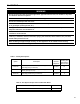
Appendix A - Figures Figure Number Page Number Figure 1 5 Minimum Clearances to Combustibles Figure 2 6 Dimensions Description Section III - Venting Figure 3 12 U.S.
Appendix B - Tables Table Number Page Number Description Section III - Venting Table 1 9 Vent System Options Table 2 9 Vent System Components Included with Boiler Table 3 10 Vent System Components Table 4 10 Vent Length Section V - Gas Piping Table 5 27 Gas Ratings Table 6 27 Specific Gravity Correction Factors for Natural Gas Table 7 28 Maximum Capacity of Schedule 40 Pipe in CFH* for Natural Gas Pressures of 0.
U.S. Boiler Company, Inc. P.O. Box 3020 Lancaster, PA 17604 1-888-432-8887 www.usboiler.