
Install Instructions


17
Vertical Venting
–
1. See Figure 28 for Blower Vent Connector
Assembly. Do not exceed maximum vent lengths.
Refer to Table 4.
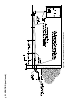
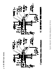
2. Installation of a vertical vent drain tee 8116304U
is required on all vertical vent applications. See
Figures 6 and 7. Attach vertical vent drain tee
directly to elbow or horizontal pipe from an elbow
immediately after vent connector.
3. Slope horizontal runs minimum ¼ inch per foot.
Slope towards vertical vent drain tee. Position weld
seams in vent pipes, in all horizontal runs, at the top
to avoid condensate from lying on the seams.
4. Install re stops where vent passes through oors,
ceilings or framed walls. The re stop must close
the opening between the vent pipe and the structure.
E. Separate Vertical Venting System - See Figures 6, 7, 8 and 9.
NOTICE
and storm collar - not supplied with boiler.
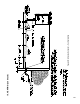
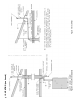
5. Whenever possible, install vent straight through
the roof. Refer to Figure 7 if offset is necessary.
Maintain minimum clearance to combustible
materials.
6. Install Vent Terminal.
a. Size roof opening to maintain minimum
clearance from combustible materials.
b. Extend vent pipe to maintain minimum vertical
and horizontal distance of twelve (12) inches
from roof surface. Allow additional vertical
distance for expected snow accumulation.
Provide brace as required. Refer to Figure 8.
c. Install storm collar on vent pipe immediately
above ashing. Apply Dow Corning Silastic 732
RTV Sealant between vent pipe and storm collar
to provide weathertight seal.
d. Attach vent terminal.
III. VENTING (continued)