
Installation Operating Instructions

33 of 60
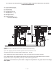
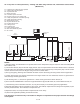
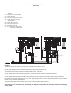
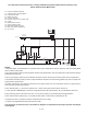
A4. 3-way RTC in Primary/Secondary - Heating and DHW using Indirect Water Heater on Primary Loop;
without Outdoor Reset (Electrical)
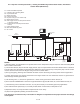
NOTES:
1) Refer to the I&O to determine correct valve orientation and actuator wiring.
2) 120 VAC supplying the RTC should be separate from the burner/boiler circuit.
3) Heat demand can be any electrical signal consisting of 24 - 240 VAC.
4) Use isolation relays for circulators greater than 1/3 HP. Use motor starters for 3 phase circulators.
5) System Pump (P3) to be operated by zone relay or other installer supplied device.
This diagram is for reference only. The installer or designer is responsible for the proper selection and design
of the system.
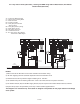
C
24 V (ac)
R
N
120 V (ac)
Class II
Transformer
L
S1
Do not apply power
10A
Boil
Ret
Com Mix OutCom
L
12 13 14 15 16
Boil
Pmp
N
6
Burnham RTC
3 5
R
9
R
10
N
11
N
4
Power
10A
24 Volt Output
7 8
Boiler
Enable
1 2
Heat
Demand
P1
Boiler
C1
CW - Closed to System
C1
CW - Open to System
NL1 L1
Z1...Z3
R
9
R
10
N
11
24 Volt Output
NL1 L1
2
1
8
7
3
4
5
6
P2
A1
Breaks on
Temp. Rise
R1
A1 = Indirect Hot Water Aquastat
C1 = Mixing Valve Actuating Motor
P1 = Boiler Circulator
P2 = Indirect Circulator
R1 = Relay
S1 = Boiler Return Sensor
Z1...Z3 = Zone Valves, Zone Relays,
Thermostats or BMS Signal