IN S TAL L AT ION , OP E R AT IN G AN D S E R V IC E IN S T R U C T ION S F OR P V G™ GA S - F I R E D BOI L E R As an ENERGY STAR® Partner, Burnham Hydronics has determined that the PVG Series meets the ENERGY STAR® guidelines for energy efficiency established by the United States Environmental Protection Agency (EPA). F o r s e rvi c e o r r e p a i rs to b o i le r, c a ll yo ur he a ti ng c o ntra c to r.
IMPORTANT INFORMATION - READ CAREFULLY NOTE: The equipment shall be installed in accordance with those installation regulations enforced in the area where the installation is to be made. These regulations shall be carefully followed in all cases. Authorities having jurisdiction shall be consulted before installations are made. All wiring on boilers installed in the USA shall be made in accordance with the National Electrical Code and/or local regulations.
WARNING This boiler requires regular maintenance and service to operate safely. Follow the instructions contained in this manual. Improper installation, adjustment, alteration, service or maintenance can cause property damage, personal injury or loss of life. Read and understand the entire manual before attempting installation, start-up operation, or service. Installation and service must be performed only by an experienced, skilled, and knowledgeable installer or service agency.
Table of Contents I. Pre-Installation................................ 6 VI. Electrical........................................ 28 II. Unpack Boiler................................. 7 VII. Modular Installation..................... 37 III. Venting............................................ 8 VIII. System Start-up............................. 39 IV. Water Piping and Trim.................. 20 IX. Service........................................... 46 V. Gas Piping.....................................
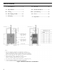
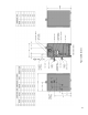
Figure 2: Dimensions
I. Pre-Installation WARNING F. Provide combustion and ventilation air in accordance If you do not follow these instructions exactly, a fire or explosion may result causing property damage or personal injury. with applicable provisions of local building codes, or: USA - National Fuel Gas Code, NFPA 54/ANSI Z223.1, Air for Combustion and Ventilation; Canada - Natural Gas or Propane Installation Code, CAN/CSA-B149.1.
by duct with the outdoors or spaces (crawl or attic) freely communicating with the outdoors. Locate one opening within twelve (12) inches of top of space. Locate remaining opening within twelve (12) inches of bottom of space. Minimum dimension of air opening is three (3) inches. Size each opening per following: space(s) of sufficient volume such that combined volume of all spaces meet criteria for unconfined space.
III. Venting WARNING Do not use this boiler with galvanized, Type 304 or Type 316 stainless steel, non metallic or any other non AL29-4C® based vent systems. Do not use a barometric damper or drafthood with this appliance. Do not use vent dampers with this boiler. Moisture and ice may form on surfaces around termination. To prevent deterioration, surfaces should be in good repair (sealed, painted, etc.).
Table 3: Burnham Vent System Components Vent System Component Equivalent Feet of Pipe Part Number 3” Dia. Pipe x 1 Ft 8116296U 4” Dia. Pipe x 1 Ft 100176-01 3” Dia. Pipe x 3 Ft 8116298U 4” Dia. Pipe x 3 Ft 100177-01 3” Dia. Pipe x 5 Ft 8116300U 4” Dia. Pipe x 5 Ft 100178-01 3” Dia. Pipe x Adjustable 8116319U 4” Dia. Pipe x Adjustable 100179-01 3” Dia. 90° Elbow 8116294U 4” Dia. 90° Elbow 100180-01 3” Dia. 45° Elbow 8116292U 4” Dia. 45° Elbow 100181-01 3” Dia.
A. Vent Guidelines Due to Removal of an Existing Boiler For installations not involving the replacement of an existing boiler, proceed to Step B. When an existing boiler is removed from a common venting system, the common venting system is likely to be too large for proper venting of the remaining appliances.
a. Minimum twelve (12) inches above grade plus normally expected snow accumulation level, or seven (7) feet above grade if located adjacent to public walkway. Do not install over public walkway where local experience indicates appliance flue gas vapor or condensate creates a nuisance or hazard. b. Minimum three (3) feet above any forced air inlet located within ten (10) feet. c. Minimum four (4) feet below, four (4) feet horizontally from, or four (4) feet above any door, window, or gravity air inlet. d.
c. Tighten locking band by HAND with a 5/16” nut driver until snug plus ¼ turn. DO NOT SECURE JOINTS WITH SHEET METAL SCREWS OR POP RIVETS. DO NOT PUNCTURE THE VENT SYSTEM! d. Once the installation is complete, operate appliance and inspect all joints to ensure that flue gases and/or liquid condensate will not escape. D. Horizontal Venting System. See Figures 4, 4A and 5. Vent Piping – 1.
Figure 4: Recommended Horizontal – Vent Installation
Figure 4A: Alternate Horizontal – Vent Installation
Figure 5: Horizontal – Vent Terminal Configuration (3” or 4” Vent)
E. Vertical Venting System - See Figures 6, 7 and 8. NOTICE Roof penetrations require the use of roof flashing and storm collar - not supplied with boiler. Vent Piping – 1. Do not exceed maximum vent lengths. Refer to Table 4. 2. Installation of a vertical vent tee 8116304U is required on all vertical vent applications. See Figures 6 and 7. Attach vertical vent drain tee directly to elbow or horizontal pipe from an elbow immediately after vent connector. 3. Slope horizontal runs minimum ¼ inch per foot.
Figure 6: Vertical Vent Installation Figure 7: Attic Offset
Extend Vent Piping to maintain minimum vertical (“X”) and minimum horizontal (“Y”) distance of twelve (12) inches from roof surface. Allow additional vertical (“X”) distance for expected snow accumulation.
F. Optional Exterior Separate Horizontal Vent Terminal Mounting – See Figure 9. 1. Do not exceed maximum vent lengths. Refer to Table 4. 2. This installation will allow a maximum of seven (7) feet vertical exterior run of the vent piping to be installed . NOTICE Exterior run to be included in equivalent vent lengths. 3. Install vent piping. a. Install vent piping for desired venting system. Refer to specific section for details for vent pipe installation. b.
IV. Water Piping and Trim WARNING Failure to properly pipe boiler may result in improper operation and damage to boiler or structure. Oxygen contamination of boiler water will cause corrosion of iron and steel boiler components, and can lead to boiler failure. Burnham’s Standard Warranty does not cover problems caused by oxygen contamination of boiler water or scale (lime) build-up caused by frequent addition of water. A.
How to Wire Ensure power is turned off to boiler. Locate the LWCO jumper wire in the factory wiring harness. Remove the jumper wire and install the LWCO wiring from LWCO Model 1100-H4 (P/N 100592-01) into the plug of the PVG factory wiring. How to Test Shut off fuel supply. Lower water level until water level is BELOW the LWCO. Generate a boiler demand by turning up thermostat. Boiler should not attempt to operate. Increase the water level by filling the system.
Figure 10A: Supply Water Manifold Piping Install pipe tee between circulator and boiler return along with second tee in supply piping as shown in Figure 11 or 12. Bypass should be same size as the supply and return lines with valves located in bypass and supply outlet as illustrated in Figure 11 or 12 in order to regulate water flow to maintain higher boiler water temperatures. After the boiler is operational (reference Section VIII.
Figure 11: Recommended Boiler Piping For Circulator Zoned Heating Systems
Figure 12: Recommended Water Piping for Zone Valve Zoned Heating Systems
V. Gas Piping Table 7 for maximum capacity of Schedule 40 pipe. Table 8 lists equivalent pipe length for standard fittings. WARNING Failure to properly pipe gas supply to boiler may result in improper operation and damage to the boiler or structure. Always assure gas piping is absolutely leak free and of the proper size and type for the connected load. An additional gas pressure regulator may be needed. Consult gas supplier. 4. Corrections for the specific gravity of natural gas can be found in Table 6.
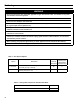
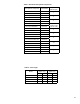
Table 7: Maximum Capacity of Schedule 40 Pipe in CFH* For Natural Gas Pressures of 0.5 psig or Less 0.3 inch w.c. Pressure Drop 0.5 inch w.c.
4. All above ground gas piping upstream from manual shut-off valve must be electrically continuous and bonded to a grounding electrode. Do not use gas piping as grounding electrode. Refer to National Electrical Code, NFPA 70. C. Pressure test. The boiler and its gas connection must be leak tested before placing boiler in operation. 1. Protect boiler gas control valve. For all testing over ½ psig, boiler and its individual shutoff valve must be disconnected from gas supply piping.
VI. Electrical DANGER Positively assure all electrical connections are unpowered before attempting installation or service of electrical components or connections of the boiler or building. Lock out all electrical boxes with padlock once power is turned off. WARNING Failure to properly wire electrical connections to the boiler may result in serious physical harm. Electrical power may be from more than one source. Make sure all power is off before attempting any electrical work.
Figure 14: Internal Boiler Wiring Schematic Diagram
NOTICE If an additional system limit is used, install in series with the auxiliary limit jumper shown in the drawing below.
D. System Controls and Wiring 1. Refer to National Electric Code or Local Electric Codes for proper size and type of wire required. Follow Code. 2. Use anti-short bushings on all wiring passing through boiler jacket, junction boxes and/or control boxes. 3. Use armored cable (BX) over all exposed line voltage wiring. 4. If an Alliance™ indirect water heater is used, use priority zoning except for Hydro-Air Systems. 5.
Figure 16: Single Heating Zone Only Wiring Schematic
NOTICE Figure 17: Single Zone System with Packaged Alliance™ Water Heater Wiring Schematic If an additional system limit is used, install in series with the auxiliary limit jumper shown in the drawing below.
Figure 18: Circulator Zoned System Wiring Schematic
Figure 19: Zone Valve Zoned System Wiring Schematic
Figure 20: Different Manufacturer’s Zone Valve Connections to Honeywell R8889 36
VII. Modular Installation A. General Guidelines 1. Read and follow all venting, combustion air, water piping, gas piping and electrical instructions contained in this manual unless otherwise instructed in this section. 2. Consult Local Building Codes or National Fuel Gas Code, NFPA 54/ANSI Z222.3 for restrictions and instructions on modular boiler installations. B. Module Sizing Burnham recommends sizing each boiler in a modular system to provide 20 % of the combined heating load where ever possible. C.
Figure 21: Modular Boiler Piping
VIII. System Start-up A. Safe operation and other performance criteria were met with gas manifold and control assembly provided on boiler when boiler underwent tests specified in American National Standard for Gas-Fired LowPressure Steam and Hot Water Boilers, ANSI Z21.13. B. Verify that the venting, water piping, gas piping and electrical system are installed properly. Refer to installation instructions contained in this manual. C.
Figure 22: Operating Instructions 40
H. Operating Instructions 1. Follow Operating Instructions to place boiler in operation. See Figure 22. 2. Electronic Ignition Modules with LED indicators. Table 10 cross-references the ignition module terminal designations to the ignition terminal Figure 23: LED Locations numbers in the wiring ladder diagrams. The yellow LED indicates the status of the flame, see Table 11. The green LED indicates the status of the system, see Table 12. See Figure 23 for LED locations.
Table 12: Green LED Status Codes Green LED Flash Code (X + Y)a Next System Action Recommended Service Action No “Call for Heat” N/A None Flash Fast Startup - Flame sense calibration N/A None Heartbeat Normal operation N/A None OFF 5 minute Retry DelayPilot flame not detected during trial for ignition Initiate new trial for ignition after retry delay completed.
Honeywell Electronic Ignition Troubleshooting Guide Figure 24: Troubleshooting Guide 43
Figure 26: 1 Inch Main Burner flame Figure 27: Pilot Burner Flame L. Check thermostat operation. Raise and lower temperature setting to start and stop boiler operation. M. Check ignition control module shut-off. Disconnect pilot lead wires from gas valve. If burners do not shutdown, determine cause of malfunction. Replace necessary items and check operation. N. Check low water cutoff (if so equipped). 1. Adjust thermostat to highest setting. Figure 25: Sequence of Operation I. Sequence of Operation.
temperature. Main burners and pilot burner should extinguish, and blower should stop. 3. Adjust limit to setting above observed temperature. Ignition sequence should begin. 4. Adjust thermostat to lowest setting. Adjust limit to desired setting. P. Adjust gas input rate to boiler. 1. Adjust thermostat to highest setting. 2. Check manifold gas pressure. See Table 5 or rating label located in the boiler’s vestibule compartment.
IX. Service DANGER This boiler uses flammable gas, high voltage electricity, moving parts, and very hot water under high pressure. Assure that all gas and electric power supplies are off and that the water temperature is cool before attempting any disassembly or service. Do not attempt any service work if gas is present in the air in the vicinity of the boiler. Never modify, remove or tamper with any control device.
2. 3. 4. 5. 6. 7. 8. 9. 10. 11. 12. 13. 14. 15. e. Mark location of Main Burner with Pilot Bracket on gas manifold. f. Hold Main Burner on throat. Lift front of burners to clear orifice. Burner which holds pilot can be removed by lifting the burner adjacent to its right first. Disconnect Vent Connector and Vent Pipe from Blower Outlet. Remove Jacket Top Panel. Disconnect the Black and Gray Silicone Tubing from the Canopy. Disconnect Wiring Harness from Blower Motor. Remove Canopy/Blower Assembly. a.
Figure 30: Flue and Burner Cleanout, 1” Burner
Table 14: Pilot Burner Location Boiler Model Main Burner with Pilot Bracket Pilot Burner Located Between Main Burners * PVG-3 2 2&3 PVG-4 3 3&4 PVG-5 4 4&5 PVG-6 5 5&6 PVG-7 6 6&7 PVG-8 7 7&8 PVG-9 8 8&9 * Main burners numbered left to right as viewed from front of boiler. 3. Start boiler and read Pressure on Manometer when boiler water temperature reaches operating temperature. Refer to Table 15 for minimum readings.
XI. Repair Parts All PVG Repair Parts may be obtained through your local Burnham Wholesale distributor. Should you require assistance in locating a Burnham distributor in your area, or have questions regarding the availability of Burnham products or repair parts, please contact Burnham Customer Service at (717) 481-8400 or Fax (717) 481-8408.
Key No. [Quantity] Part Number Description PVG-3 PVG-4 PVG-5 PVG-6 PVG-7 PVG-8 PVG-9 61707031 61707041 61707051 61707061 61707071 61707081 61707091 [5] 71707003 [6] 71707003 [7] 71707003 1.
Key No. Description [Quantity] Part Number PVG-3 PVG-4 PVG-5 PVG-6 PVG-7 PVG-8 PVG-9 2.
Key No. Description [Quantity] Part Number PVG-3 PVG-4 PVG-5 PVG-6 PVG-7 PVG-8 PVG-9 3.
Key No. Description [Quantity] Part Number PVG-3 PVG-4 PVG-5 PVG-6 PVG-7 PVG-8 PVG-9 Canopy Assembly - Sea Level 61107031 61107041 61107051 61107061 61107071 61107081 61107091 Canopy Assembly - High Altitude 61107032 61107042 61107052 61107062 61107072 61107082 61107092 4.
Key No. Description [Quantity] Part Number PVG-3 PVG-4 PVG-5 PVG-6 PVG-7 PVG-8 PVG-9 5.
Key No. Description [Quantity] Part Number PVG-3 PVG-4 PVG-5 PVG-6 PVG-7 PVG-8 PVG-9 6.
Key No. Description [Quantity] Part Number PVG-3 PVG-4 PVG-5 PVG-6 PVG-7 PVG-8 PVG-9 7.
Key No. Description [Quantity] Part Number PVG-3 PVG-4 PVG-5 PVG-6 PVG-7 PVG-8 PVG-9 8.
Important Product Safety Information Refractory Ceramic Fiber Product Warning: The Repair Parts list designates parts that contain refractory ceramic fibers (RCF). RCF has been classified as a possible human carcinogen. When exposed to temperatures about 1805°F, such as during direct flame contact, RCF changes into crystalline silica, a known carcinogen. When disturbed as a result of servicing or repair, these substances become airborne and, if inhaled, may be hazardous to your health.
Limited Warranty FOR RESIDENTIAL CAST IRON WATER BOILERS Subject to the terms and conditions set forth below, U.S. Boiler™ Co., Inc. Lancaster, Pennsylvania hereby extends the following limited warranties to the original owner of a residential grade water boiler manufactured and shipped on or after July 1,1991: ONE YEAR LIMITED WARRANTY ON RESIDENTIAL GRADE WATER BOILERS U.S. Boiler Co., Inc.
IN S TAL L AT ION , OP E R AT IN G AN D S E R V IC E IN S T R U C T ION S F OR S C G™ GA S - F I R E D BOI L E R As an ENERGY STAR® Partner, Burnham Hydronics has determined that the SCG meets the ENERGY STAR® guidelines for energy efficiency established by the United States Environmental Protection Agency (EPA). F o r s e rvi c e o r r e p a i rs to b o i le r, c a ll yo ur he a ti ng c o ntra c to r.
IMPORTANT INFORMATION - READ CAREFULLY NOTE: The equipment shall be installed in accordance with those installation regulations enforced in the area where the installation is to be made. These regulations shall be carefully followed in all cases. Authorities having jurisdiction shall be consulted before installations are made. All wiring on boilers installed in the USA shall be made in accordance with the National Electrical Code and/or local regulations.
WARNING This boiler requires regular maintenance and service to operate safely. Follow the instructions contained in this manual. Improper installation, adjustment, alteration, service or maintenance can cause property damage, personal injury or loss of life. Read and understand the entire manual before attempting installation, start-up operation, or service. Installation and service must be performed only by an experienced, skilled, and knowledgeable installer or service agency.
Table of Contents I. Pre-Installation................................ 6 VI. Electrical........................................ 53 II. Unpack Boiler................................. 7 VII. Modular Installation..................... 62 III. Venting/Air Intake Piping............... 8 VIII. System Start-up............................. 64 IV. Water Piping and Trim.................. 45 IX. Service........................................... 71 V. Gas Piping..................................... 50 X.
Figure 2: Dimensions
I. Pre-Installation WARNING F. Provide combustion and ventilation air in accordance If you do not follow these instructions exactly, a fire or explosion may result causing property damage or personal injury. with applicable provisions of local building codes, or: USA - National Fuel Gas Code, NFPA 54/ANSI Z223.1, Air for Combustion and Ventilation; Canada - Natural Gas or Propane Installation Code, CAN/CSA-B149.1.
c. Horizontal ducts. Minimum free area of one (1) square inch per 2,000 Btu per hour input of all equipment in space. Duct cross-sectional area shall be same as opening free area. Alternate method for boiler located within confined space. Use indoor air if two permanent openings communicate directly with additional space(s) of sufficient volume such that combined volume of all spaces meet criteria for unconfined space.
III. Venting / Air Intake Piping WARNING Do not use this boiler with galvanized, Type 304 or Type 316 stainless steel, non metallic or any other non AL29-4C® based vent systems. Do not use a barometric damper or drafthood with this appliance. Do not use vent dampers with this boiler. Moisture and ice may form on surfaces around termination. To prevent deterioration, surfaces should be in good repair (sealed, painted, etc.).
Table 2: Vent System Components Included with Boiler Vent System Components Part Number Gasketed Vent Terminal 3” Horizontal (SCG-3 thru SCG-7) 8110701 Gasketed Vent Terminal 4” Horizontal (SCG-8 & SCG 9) 8110702 Disc Air Intake - 3” (SCG-3 & SCG-4) 6116045 Disc Air Intake - 4” (SCG-5 & SCG-6) 6116044 Air Intake - 5” (SCG-7 thru SCG-9) 6116063 Table 3: Burnham Vent System and Air Intake System Components Vent System Component Part Number 3” Dia. Pipe x 1 Ft 8116296U 4” Dia.
A. Vent Guidelines Due to Removal of an Existing Boiler For installations not involving the replacement of an existing boiler, proceed to Step B. When an existing boiler is removed from a common venting system, the common venting system is likely to be too large for proper venting of the remaining appliances.
with at least one side open, similar to a joist bay application. Use double wall thimble [Burnham Part No. 8116115 (3”), 100185-01 (4”)] when penetrating a combustible wall. 9. Do not install venting system components on the exterior of the building except as specifically required by these instructions. The vent termination location is restricted as follows: a.
a. Wipe the male end of each joint using an alcohol pad to remove any dirt and grease. b. Align weld seams in pipes and use a slight twisting motion to FULLY insert male end into female end of joint. Ensure bead in male end of pipe is below locking band and rest against the end of the female pipe. Verify the factoryinstalled gasket is not dislodged or cut. c. Tighten locking band by HAND with a 5/16” nut driver until snug plus ¼ turn. DO NOT SECURE JOINTS WITH SHEET METAL SCREWS OR POP RIVETS.
13 Figure 4A: Recommended Separate Horizontal – Vent/Air Intake Installation
14 Figure 4B: Alternate Separate Horizontal – Vent/Air Intake Installation
15 Figure 5A: Separate Horizontal – Vent/Air Intake Terminal Configuration (SCG-3 thru 7)
16 Figure 5B: Separate Horizontal – Vent/Air Intake Terminal Configuration (SCG-8 and 9)
E. Separate Vertical Venting System - See Figures 6, 7, 8A, 8B and 9. NOTICE Roof penetrations require the use of roof flashing and storm collar - not supplied with boiler. Vertical Venting – 1. See Figure 43 on Page 72 for Blower Vent Connector Assembly. Do not exceed maximum vent lengths. Refer to Table 4. 2. Installation of a vertical vent drain tee 8116304U is required on all vertical vent applications. See Figures 6 and 7.
d. Install storm collar on air intake pipe immediately above flashing. Apply Dow Corning Silastic 732 RTV Sealant between air intake pipe and storm collar to provide weathertight seal. e. All exposed air intake piping must be constructed of corrosion resistant material such as aluminum, stainless steel or PVC. 18 15. Seal all joints airtight, using silicone caulk or selfadhesive aluminum tape. 16. Install Air Intake Terminal: Vertical - Insert intake piping into intake terminal collar.
19 Figure 6: Vertical Vent Installation Figure 7: Attic Offset
20 Extend Vent/Air Intake Piping to maintain minimum vertical (“X”) and minimum horizontal (“Y”) distance of twelve (12) inches from roof surface. Allow additional vertical (“X”) distance for expected snow accumulation.
21 Extend Vent/Air Intake Piping to maintain minimum vertical (“X”) and minimum horizontal (“Y”) distance of twelve (12) inches from roof surface. Allow additional vertical (“X”) distance for expected snow accumulation.
Figure 9: Vertical Air Intake Piping 22
F. Combination Horizontal Venting System –SCG-3 Through SCG-6 ONLY – See Figures 10 and 11. 1. Do not exceed maximum vent/air intake lengths. Refer to Table 4. NOTICE This vent system requires components not supplied with the boiler. 2. Install Combination Vent/Air Terminal. See Figure 11. a. After determining the location with reference to Section B - General Venting Guidelines, cut a 6-1/8 inch square opening in the wall for the air box sub-assembly which is 6 inch square. b.
c. From exterior of building, insert air box subassembly into square opening. Push air box inward until wall flange is against wall, check for level and mark the location of the four (4) securing holes on the exterior wall. Remove air box from wall. d. Drill four (4) pilot holes, properly sized for the non-corrosive fasteners (stainless steel, brass, or aluminum) to be used to secure the wall flange to the exterior wall. (Securing screws not supplied with kit.) e.
25 Figure 10: Combination Horizontal – Vent/Air Installation (SCG-3 thru 6)
26 Figure 11: Combination Horizontal – Vent/Air Terminal Installation (SCG-3 thru 6)
G. Combination Vertical Venting System – SCG-3 Through SCG-6 ONLY – See Figures 12, 13 and 14. NOTICE This vent system requires components not supplied with the boiler.
1. Saf-T Vent SC is an advanced concentric vent system designed for zero clearance installation in residential applications. The inner wall is constructed from superferritic AL29-4C® stainless steel. The outer wall is also constructed from stainless steel, providing durability and a lasting finish. the system in place. A continuous straight-line pitch of at least ¼” (2°) to the foot on horizontal runs must be maintained in order to properly rid the system of the corrosive condensate. 5.
• • • For a venting system that extends through any zone above that on which the connected appliance is located (except for one and two family dwellings), the vent system shall be enclosed with an enclosure having a fire resistance rating equal to or greater than that of the floor or roof assemblies through which it passes. Design any enclosure to permit inspection of the system. Do not place any type of insulation in any required clearance spaces surrounding the vent system. 6.
7. Joint Assembly Instructions: a. Before joining the sections or fittings together, use an alcohol pad to wipe the joint area of both ends of the inner pipe. This will remove any foreign matter which may affect the integrity of the seal. Install the system with the female ends (ends with the red seal) pointing away from the appliance. (Unless specified differently by the appliance manufacturer.) b. Insert the male end of the inner pipe into the female end of the previous section.
8. Straight Sections Cut To Length: If a custom length of SC is necessary, a standard vent section can be cut. a. Measure the distance of the length needed, taking the measurement from the end of one of the outer jackets to the beginning of the other outer jacket on the section to connect to, (A to B on diagram). b. Select a section that is longer than the required length. c. It will be necessary to disassemble the vent prior to cutting. Stand the section on end with the holes up.
9. Air Intake Connections for Direct Vent and Sealed Combustion Appliances*: The Air Intake Tee may be used on approved direct vent and sealed combustion appliances that have separate (nonconcentric) air intake and flue exhaust collars. The male end of the tee connects to EZ Seal appliance adapters and the tee takeoff/snout connects to the appliance air intake.
11. Horizontal Supports: Saf-T Vent SC must have supports for every six (6) feet of horizontal run and after every transition from vertical to horizontal. Support hangers by themselves do not maintain the necessary clearances to combustible materials; be sure to consider clearances when planning the system. The supports must be secured to solid material using at least #10 fasteners. Do not fasten supports to drywall sheathing without using hollow wall anchors.
Support Clamp, (4_ _27SS): Support clamps are sold in pairs and can be clamped around the vent and suspended from a rod or cable. They can be used singularly as a saddle clamp to rest the vent in and suspended from two (2) rods or cables. Support Legs Rotated Horizontally: Support legs can be used on horizontal runs by rotating the clamp at the rivet connection. The legs can be cut to shorter lengths if necessary.
Fire Stop/Wall Thimble/Support, (SC_ _FS): • The Saf-T Vent SC Fire Stop can be used as a firestop, a wall thimble, or as a support plate. • To use as a Wall Thimble prepare an opening according to the chart below. Remove any insulation from the opening, using additional framing if necessary. Attach the plate over the center of the opening using appropriate fasteners.
Vertical Terminations, (SC_ _VT): Install the vertical termination adapter into the last vent section and secure with the three (3) self-tapping screws provided. If the exhaust termination needs to be extended, a section of EZ Seal vent can be connected directly to the vertical termination adapter. Seal weather exposed joints of the outer jacket with foil tape or an exterior grade silicone sealant. To allow for inspection of the system, do not seal the exhaust termination.
H. Indoor Air Installation – See Figures 12, 13, 14, 15 and 16. 1. Do not exceed maximum vent length. Refer to Table 4. Horizontal – 2. Maintain minimum ¼ inch per foot slope in horizontal runs. Position weld seams in vent pipes, in all horizontal runs, at the top to avoid condensate from lying on the seams. 3 Recommended horizontal installation consists of vent being sloped down away from boiler. See Figure 12. 4. Alternate horizontal installation consists of vent being sloped down toward the boiler.
38 Figure 12: Recommended Separate Horizontal - Vent Installation
39 Figure 13: Alternate Separate Horizontal - Vent Installation
Figure 14: Optional Indoor Air - Vent Terminal Installation Figure 15: Indoor Air - Vertical Vent Terminal Installation Extend Vent/Air Intake Piping to maintain minimum vertical (“X”) and minimum horizontal (“Y”) distance of twelve (12) inches from roof surface. Allow additional vertical (“X”) distance for expected snow accumulation.
I. Optional Exterior Separate Horizontal Vent/Air Intake Terminal Mounting – See Figures 17, 18, 19, 20, 21 and 22. 1. Do not exceed maximum vent/air intake lengths. Refer to Table 4. 2. This installation will allow a maximum of seven (7) feet vertical exterior run of the vent/air intake piping to be installed on separate horizontal venting and indoor air horizontal venting. NOTICE Exterior run to be included in equivalent vent/air intake lengths. 3. Install vent piping. a.
Figure 18: Optional Separate Horizontal Air 5” Intake Terminal Installation Figure 19: Optional Separate Horizontal 3” Vent Terminal Installation 42
Figure 20: Optional Separate Horizontal 4” Vent Terminal Installation Figure 21: Optional Separate Horizontal 3” Vent Terminal Installation (Indoor Air) 43
Figure 22: Optional Separate Horizontal 4” Vent Terminal Installation (Indoor Air) 44
IV. Water Piping and Trim WARNING Failure to properly pipe boiler may result in improper operation and damage to boiler or structure. Oxygen contamination of boiler water will cause corrosion of iron and steel boiler components, and can lead to boiler failure. Burnham’s Standard Warranty does not cover problems caused by oxygen contamination of boiler water or scale (lime) build-up caused by frequent addition of water. A.
How to Wire Ensure power is turned off to boiler. Locate the LWCO jumper wire in the factory wiring harness. Remove the jumper wire and install the LWCO wiring from LWCO Model 1100-H4 (P/N 100592-01) into the plug of the SCG factory wiring. How to Test Shut off fuel supply. Lower water level until water level is BELOW the LWCO. Generate a boiler demand by turning up thermostat. Boiler should not attempt to operate. Increase the water level by filling the system.
Figure 24: Supply Water Manifold Piping Install pipe tee between circulator and boiler return along with second tee in supply piping as shown in Figure 25 or 26. Bypass should be same size as the supply and return lines with valves located in bypass and supply outlet as illustrated in Figure 25 or 26 in order to regulate water flow to maintain higher boiler water temperatures. After the boiler is operational (reference Section VIII.
48 Figure 25: Recommended Water Piping for Circulator Zoned Heating Systems
49 Figure 26: Recommended Water Piping for Zone Valve Zoned Heating Systems
V. Gas Piping 3. Length of piping and number of fittings. Refer to Table 7 for maximum capacity of Schedule 40 pipe. Table 8 lists equivalent pipe length for standard fittings. WARNING Failure to properly pipe gas supply to boiler may result in improper operation and damage to the boiler or structure. Always assure gas piping is absolutely leak free and of the proper size and type for the connected load. An additional gas pressure regulator may be needed. Consult gas supplier. 4.
Table 7: Maximum Capacity of Schedule 40 Pipe in CFH* For natural Gas Pressures of 0.5 psig or Less 0.3 Inch w.c. Pressure Drop 0.5 Inch w.c.
4. All above ground gas piping upstream from manual shut-off valve must be electrically continuous and bonded to a grounding electrode. Do not use gas piping as grounding electrode. Refer to National Electrical Code, NFPA 70. C. Pressure test. The boiler and its gas connection must be leak tested before placing boiler in operation. 1. Protect boiler gas control valve. For all testing over ½ psig, boiler and its individual shutoff valve must be disconnected from gas supply piping.
VI. Electrical DANGER Positively assure all electrical connections are unpowered before attempting installation or service of electrical components or connections of the boiler or building. Lock out all electrical boxes with padlock once power is turned off. WARNING Failure to properly wire electrical connections to the boiler may result in serious physical harm. Electrical power may be from more than one source. Make sure all power is off before attempting any electrical work.
54 Figure 28: Internal Boiler Wiring Schematic Diagram
NOTICE If an additional system limit is used, install in series with the auxiliary limit jumper shown in the drawing below.
D. System Controls and Wiring 1. Refer to National Electric Code or Local Electric Codes for proper size and type of wire required. Follow Code. 2. Use anti-short bushings on all wiring passing through boiler jacket, junction boxes and/or control boxes. 3. Use armored cable (BX) over all exposed line voltage wiring. 4. If an Alliance™ indirect water heater is used, use priority zoning except for Hydro-Air Systems. 5.
57 Figure 30: System Wiring Schematic for Single Zone Space Heating Only
NOTICE Figure 31: Single Zone System with Packaged Alliance™ Water Heater Wiring Schematic If an additional system limit is used, install in series with the auxiliary limit jumper shown in the drawing below.
59 Figure 32: Circulator Zoned System Wiring Schematic
60 Figure 33: Zone Valve Zoned System Wiring Schematic
Figure 34: Different Manufacturer’s Zone Valve Connections to Honeywell R8889 61
VII. Modular Installation A. General Guidelines 1. Read and follow all venting, combustion air, water piping, gas piping and electrical instructions contained in this manual unless otherwise instructed in this section. 2. Consult Local Building Codes or National Fuel Gas Code, NFPA 54/ANSI Z222.3 for restrictions and instructions on modular boiler installations. B. Module Sizing Burnham recommends sizing each boiler in a modular system to provide 20 % of the combined heating load where ever possible. C.
63 Figure 35: Modular Boiler Gas Piping
VIII. System Start-up A. Safe operation and other performance criteria were met with gas manifold and control assembly provided on boiler when boiler underwent tests specified in American National Standard for Gas-Fired LowPressure Steam and Hot Water Boilers, ANSI Z21.13. B. Verify that the venting, water piping, gas piping and electrical system are installed properly. Refer to installation instructions contained in this manual. C.
Figure 36: Operating Instructions 65
H. Operating Instructions. 1. Follow Operating Instructions to place boiler in operation. See Figure 36. 2. Electronic Ignition Modules with LED indicators. Table 10 cross-references the ignition module terminal designations to the ignition terminal Figure 37: LED Locations numbers in the wiring ladder diagrams. The yellow LED indicates the status of the flame, see Table 11. The green LED indicates the status of the system, see Table 12. See Figure 37 for LED locations.
Table 12: green Led status codes Green LED Flash Code (X + Y)a Next System Action Recommended Service Action No “Call for Heat” N/A None Flash Fast Startup - Flame sense calibration N/A None Heartbeat Normal operation N/A None OFF 5 minute Retry DelayPilot flame not detected during trial for ignition Initiate new trial for ignition after retry delay completed.
Honeywell Electronic Ignition Troubleshooting Guide Figure 38: Troubleshooting Guide 68
Figure 40: 1 Inch Main Burner flame Figure 41: Pilot Burner Flame tipping. Orange-yellow streaks should not be confused with true yellow tipping. L. Check thermostat operation. Raise and lower temperature setting to start and stop boiler operation. M. Check ignition control module shut-off. Disconnect Figure 39: Sequence of Operation pilot lead wires from gas valve. If burners do not shutdown, determine cause of malfunction. Replace necessary items and check operation. N.
O. Check limit. 1. Adjust thermostat to highest setting. 2. Observe temperature gauge. When temperature is indicated, adjust limit to setting below observed temperature. Main burners and pilot burner should extinguish, and blower should stop. 3. Adjust limit to setting above observed temperature. Ignition sequence should begin. 4. Adjust thermostat to lowest setting. Adjust limit to desired setting. P. Adjust gas input rate to boiler. 1. Adjust thermostat to highest setting. 2. Check manifold gas pressure.
IX. Service DANGER This boiler uses flammable gas, high voltage electricity, moving parts, and very hot water under high pressure. Assure that all gas and electric power supplies are off and that the water temperature is cool before attempting any disassembly or service. Assure that all gas valves and electrical disconnect switches are off before attempting any disassembly or service. Do not attempt any service work if gas is present in the air in the vicinity of the boiler.
d. e. f. g. 2. 3. 4. 5. 6. 7. 8. 9. 10. 11. 12. Remove wires to Flame Roll-out Switch. Remove air diffuser screen. Remove Burner Access Panel. Mark location of Main Burner with Pilot Bracket on gas manifold. h. Hold Main Burner on throat. Lift front of burners to clear orifice. Burner which holds pilot can be removed by lifting the burner adjacent to its right first. Disconnect Vent Connector and Vent Pipe from Blower Outlet Remove Jacket Top Panel.
73 Figure 44: Flue and Burner Cleanout, 1” Burner
E. Main Burners and Firebox. NOTE: If switch drops-out before boiler reaches temperature or if pressure differential readings are below minimums shown in Table 15, check for cracks in hose or contact your nearest Burnham representative. 1. Vacuum firebox. Exercise care - do not damage base insulation. 2. Clean main burners. Brush top of burners with soft bristle brush. See Figure 44. Vacuum to remove any dirt and lint. 4. Stop boiler, remove manometer and reconnect hoses to differential pressure switch.
THIS PAGE LEFT INTENTIONALLY BLANK 75
76
77
XI. Repair Parts All SCG Repair Parts may be obtained through your local Burnham Wholesale distributor. Should you require assistance in locating a Burnham distributor in your area, or have questions regarding the availability of Burnham products or repair parts, please contact Burnham Customer Service at (717) 481-8400 or Fax (717) 481-8408.
Key No. Description [Quantity] Part Number SCG-3 SCG-4 SCG-5 SCG-6 SCG-7 SCG-8 SCG-9 61707031 61707041 61707051 61707061 61707071 61707081 61707091 (5) 71707003 (6) 71707003 (7) 71707003 1.
80
Key No. Description [Quantity] Part Number SCG-3 SCG-4 SCG-5 SCG-6 SCG-7 SCG-8 SCG-9 2.
82
Key No. Description [Quantity] Part Number SCG-3 SCG-4 SCG-5 SCG-6 SCG-7 SCG-8 SCG-9 2.
84
Key No. Description [Quantity] Part Number SCG-3 SCG-4 SCG-5 SCG-6 SCG-7 SCG-8 SCG-9 Canopy Assembly - Sea Level 61107031 61107041 61107051 61107061 61107071 61107081 61107091 Canopy Assembly - High Altitude 61107032 61107042 61107052 61107062 61107072 61107082 61107092 4.
86
Key No. Description [Quantity] Part Number SCG-3 SCG-4 SCG-5 SCG-6 SCG-7 SCG-8 SCG-9 5.
88
Key No. Description [Quantity] Part Number SCG-3 SCG-4 SCG-5 SCG-6 SCG-7 SCG-8 SCG-9 6.
90
Key No. Description [Quantity] Part Number SCG-3 SCG-4 SCG-5 SCG-6 SCG-7 SCG-8 SCG-9 7.
Key No. Description [Quantity] Part Number SCG-3 SCG-4 SCG-5 SCG-6 SCG-7 SCG-8 SCG-9 8.
Important Product Safety Information Refractory Ceramic Fiber Product Warning: The Repair Parts list designates parts that contain refractory ceramic fibers (RCF). RCF has been classified as a possible human carcinogen. When exposed to temperatures about 1805°F, such as during direct flame contact, RCF changes into crystalline silica, a known carcinogen. When disturbed as a result of servicing or repair, these substances become airborne and, if inhaled, may be hazardous to your health.
SERVICE RECORD DATE 94 SERVICE PERFORMED
SERVICE RECORD DATE SERVICE PERFORMED 95
Limited Warranty FOR RESIDENTIAL CAST IRON WATER BOILERS water boiler for its intended purposes and its maintenance accordance with U. S. Boiler Co., Inc. recommendations and hydronics industry standards.