
Installation & Operating Manual

11
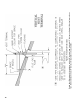
a. Minimum twelve (12) inches above grade plus
normally expected snow accumulation level, or
seven (7) feet above grade if located adjacent
to public walkway. Do not install over public
walkway where local experience indicates
appliance ue gas vapor or condensate creates a
nuisance or hazard.
b. Minimum three (3) feet above any forced air
inlet located within ten (10) feet.
c. Minimum four (4) feet below, four (4) feet
horizontally from, or four (4) feet above any
door, window, or gravity air inlet.
d. Minimum four (4) feet horizontally from electric
meters, gas meters, regulators, and relief valves.
This distance may be reduced if equipment is
protected from damage due to condensation or
vapor by enclosure, overhangs, etc.
e. Minimum twelve (12) inches from overhang or
corner of building.
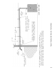
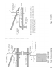
9. Enclose vent passing through occupied or
unoccupied spaces above the boiler with material
having a re resistance rating of at least equal to the
rating of the adjoining oor or ceiling. Maintain
minimum clearances to combustible materials. See
Figure 1.
Note: For one or two family dwellings, re
resistance rating requirement may not need to be
met, but is recommended.
10. Plan venting system to avoid possible contact with
plumbing or electrical wires. Start at vent connector
on top of boiler and work towards vent terminal.
11. Once a vent pipe manufacturer and system is chosen
never mix and match vent systems.
12. If a non-standard length pipe is required:
Gasketed Vent System: The use of the adjustable
length pipe (P/N 8116319U) is recommended to
complete a non-standard pipe length. This pipe
requires a minimum installed length of 12¾ inch
and can adjust across a 7 inch gap up to a maximum
of 19¾ inch long. (Note for the adjustable pipe
the installed length should be measured from the
centerline of the bead on the male end of the rst
pipe to the end of the female pipe excluding the
locking band of the second pipe with a single
gasket.) Only in the event the adjustable length pipe
is not sufcient a standard length pipe may be cut
using the procedure outlined below for the Gasket-
Less Vent System.
WARNING
Never exceed maximum installed length of 19¾
inches for adjustable length pipe.
Risk of ue gas leakage is possible.
NOTICE
Cut must be square with pipe and led or
sanded smooth before joining. Carefully ensure
roundness of cut pipe by hand with gloves before
installing. Seal joint with RTV specied in this
manual.
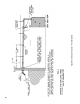
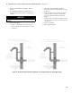
C. Install Vent Pipe, Burnham Gasketed Vent System.
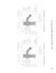
1. Procedure for Joining Burnham Gasketed Vent Pipe
and Fittings. See Figure 3.
a. Wipe the male end of each joint using an alcohol
pad to remove any dirt and grease.
b. Align weld seams in pipes and use a slight
twisting motion to FULLY insert male end into
female end of joint. Ensure bead in male end
of pipe is below locking band and rest against
the end of the female pipe. Verify the factory-
installed gasket is not dislodged or cut.
Figure 3: Burnham Gasketed Vent Joint Detail