
Installation & Operating Manual


22
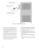
Install pipe tee between circulator and boiler return
along with second tee in supply piping as shown in
Figure 11 or 12. Bypass should be same size as the
supply and return lines with valves located in bypass
and supply outlet as illustrated in Figure 11 or 12 in
order to regulate water ow to maintain higher boiler
water temperatures.
After the boiler is operational (reference Section VIII.
System Start-Up) set by-pass and boiler supply valves
to half throttle position to start. Operate boiler until
system water temperature reaches normal operating
range.
Adjust valves to provide 180° to 200°F supply water
temperature. Opening the boiler supply valve will raise
system temperature, while opening the by-pass valve
will lower system supply temperature.
J. After the boiler and system have been cleaned and
ushed, and before relling the entire system add
appropriate water treatment chemicals, if necessary, to
bring the pH between 7 and 11.
K. If it is required to perform a long term pressure
test of the hydronic system, the boiler should rst be
isolated to avoid a pressure loss due to the escape of air
trapped in the boiler.
To perform a long term pressure test including the
boiler, ALL trapped air must rst be removed from the
boiler.
A loss of pressure during such a test, with no visible
water leakage, is an indication that the boiler contained
trapped air.
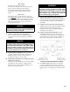
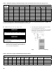
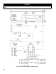
Figure 10A: Supply Water Manifold Piping