
Installation & Operating Manual


47
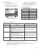
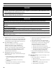
Figure 28: Silicone Tubing Assembly
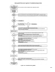
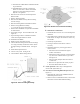
Figure 29: Blower Vent Connector Assembly
e. Mark location of Main Burner with Pilot Bracket
on gas manifold.
f. Hold Main Burner on throat. Lift front of
burners to clear orice. Burner which holds
pilot can be removed by lifting the burner
adjacent to its right rst.
2. Disconnect Vent Connector and Vent Pipe from
Blower Outlet.
3. Remove Jacket Top Panel.
4. Disconnect the Black and Gray Silicone Tubing
from the Canopy.
5. Disconnect Wiring Harness from Blower Motor.
6. Remove Canopy/Blower Assembly.
a. Loosen the (4) screws from Canopy.
7. Remove Flue Gas Bafes. Inspect Flue Gas Bafes
for deterioration.
8. Inspect ue passages. Clean with ue brush. See
Figure 30.
9. Inspect heating surface in combustion chamber.
Clean with straight handle wire brush.
10. Install Flue Gas Bafes.
11. Replace Canopy Assembly and seal.
12. Connect Silicone Tubing between Pressure Fittings
on Canopy Assembly and Pressure Switch. Route
through bushings in Vestibule Panel . See Figure
28.
13. Install Jacket Top Rear Panel.
14. Connect vent system. See Figure 29.
15. Connect Blower Motor Wiring Harness
E. Main Burners and Firebox.
1. Vacuum rebox. Exercise care - do not damage base
insulation.
2. Clean main burners. Brush top of burners with soft
bristle brush. See Figure 30. Vacuum to remove any
dirt and lint.
3. Vacuum tip of pilot burner.
4. Check gas orices for lint and dirt. Clean as
necessary.
5. Install main burners by reversing procedure to
remove burners.
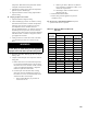
a. Pilot burner must be installed in original
location. See Table 14.
b. Main burners must be properly secured in burner
tray slot at rear of rebox and over gas orice.
See Figure 30.
c. Pilot gas supply and pilot lead wires must be
reconnected.
d. Burner access panel must be securely in place.
e. Reconnect Flame Roll-out wires.
F. Check operation. Follow steps G through P from
Section VIII: System Start-up.
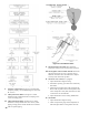
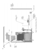
G. Procedure for measuring differential pressure (See
Figure 31).
1. With boiler off, remove Gray and Black Hoses at
differential pressure switch.
2. With tees and ¼ inch aluminum stubs, connect water
manometer as shown with additional tubing.