
X-2 User Information Manual


3
Basic Operation
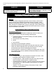
CAUTION
Should overheating occur or the gas supply fail to shut off, do not turn off or disconnect the electrical
supply to the pump. Instead, shut off the gas supply at a location external to the appliance.
Do not use this boiler if any part has been under water. Immediately call a qualied service technician
to inspect the boiler and to replace any part of the control system and any gas control which has been
under water.
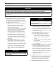
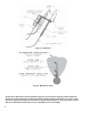
A. General. This water boiler is equipped with controls
for proper operation. All controls must be in proper
working order. Contact a qualied service agency to
provide annual maintenance as specied in Installation,
Operating and Service Instructions.
1. Limit. See Figure 1. A device which automatically
interrupts boiler operation when the water
temperature exceeds the set point. Maximum
allowable temperature is 220°F.
Original equipment with this boiler is an Intelligent
Hydronic Control (IHC) and Limit Rated Sensor
combination. The IHC shuts off boiler main
burners when boiler water temperature exceeds
pre-programmed IHC water temperature set point.
Boiler main burners will re-light automatically,
providing the call for heat is present, when boiler
water temperature falls below pre-programmed
control water temperature set point less the set point
differential.
2. Flame Rollout Switch. See Figure 1. A device
which automatically interrupts boiler operation
when ames or excessive heat are present in the
combustion area enclosure. The control is a single
use device. The control is located in the combustion
area enclosure. If the control was activated to
interrupt boiler operation, do not attempt to place
boiler in operation. Contact a qualied service
agency.
WARNING
Service on this boiler should be undertaken only
by trained and skilled personnel from a qualied
service agency.
WARNING
Do not reset Blocked Vent Switch unless a
qualied service agency has determined and
corrected the cause of any blockage in the vent
system or chimney.
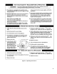
3. Blocked Vent Switch See Figure 1. A device
which automatically interrupts boiler operation
when excessive vent system blockage occurs. If the
control was activated to interrupt boiler operation,
do not attempt to place boiler in operation. Contact
a qualied service agency.
4. Electronic Ignition System - see Figure 1. The
Electronic Ignition (EI) System consists of:
a. a solid state ignition control with integral
ignition module to initiate, monitor and stop
burner operation. The IHC performs this
function.
b. a combination gas valve to regulate gas ow to
the main burners.
c. a pilot burner to provide the ignition source for
the main burners.
5. LWCO (if equipped). See Figure 1. The IDL 1200
Low Water Cut-Off is designed to protect from
potentially damaging low water conditions in the
boiler. In the event of a low water condition, the
amber "LOW WATER" LED will turn on and the
control will shut down the burner. If the control
was activated to interrupt boiler operation, do not
attempt to place boiler in operation. Contact a
qualied service agency.
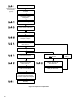
B. Instructions to place the boiler in operation and to turn
off the boiler are shown on the Operating Instruction
Label posted on the inside of the front door. The
Operating Instruction Label is shown in Figure 2.
C. The Sequence of Operation is shown in Figure 3.