BURR KING MFG. CO., INC 1220 Tamara Lane Warsaw, MO 65355 www.burrking.
BURR KING MFG. CO., INC. 1220 TAMARA LANE WARSAW MO 65355 WWW.BURRKING.COM (660) 438-8998 (800) 621-2748 FAX (660) 438-8991 Safe operation and good practice use of your BK-75 dust collection system April 2001 The BK-75 dust collection system is designed to accept one dust inlet. Dust is drawn into the BK-75 by its onboard air suction system. The air stream and dust is passed through a filter bank where a significant amount of the dust is removed from the air stream.
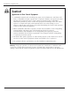
Donaldson Company, Inc. Caution! Application of Dust Control Equipment • Combustible materials such as buffing lint, paper, wood, aluminum or steel dust, weld fume, or flammable solvents represent fire or explosion hazards. Use special care when selecting and operating all dust or fume collection equipment when combustible materials are present to protect workers and property from damage due to fire and/or explosion.
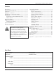
Cabinet Dust Collector, Series 50 to 80 Contents Description ........................................................... 4 Purpose and Intended Use .................................... 4 Operation ............................................................. 5 Inspection on Arrival ........................................... 6 Installation Codes and Procedures ....................... 6 Installation ........................................................... 6 Site Selection, Grade-Mounted Units ...........
Donaldson Company, Inc. Description Purpose and Intended Use Cabinet Series 50 to 80 dust collectors are selfcontained, intermittent-duty collectors with envelope-style filters. Using the EZ Filter Pack™ filter system, Cabinet series collectors provide highly efficient, low maintenance air cleaning. Filters are cleaned using the standard manual filter shaker or an optional motorized filter shaker which cleans the filters automatically each time the unit is turned off.
Cabinet Dust Collector, Series 50 to 80 Operation During normal operation, dust-laden air enters the unit through the dirty-air inlet and passes through the unit where the dust collects on the outside surface of the filter media. As dust collects on the filter surfaces, a dust cake forms, which actually improves the efficiency of the filters. The greater the amount of dust cake accumulated, the higher the efficiency of the filter.
Donaldson Company, Inc. Inspection on Arrival Installation 1. Inspect unit on delivery. Site Selection, Grade-Mounted Units 2. Report any damage to the delivery carrier. 3. Request a written inspection report from the Claims Inspector to substantiate claim. 4. File claims with the delivery carrier. 5. Compare unit received with description of product ordered. 1. The unit can be located on a reinforced concrete foundation or rooftop. 2.
Cabinet Dust Collector, Series 50 to 80 Electrical Wiring Rigging Instructions 1. All electrical wiring and connections, including electrical grounding, should be made in accordance with the National Electric Code, NFPA No. 70-latest edition. SuÖÖested Tools & Equipment 2. Check local ordinances for additional requirements that apply. 3. The appropriate wiring schematic and electrical rating must be used. See unit’s rating plate for required voltage. 4.
Donaldson Company, Inc.
Cabinet Dust Collector, Series 50 to 80 Standard Equipment Optional Equipment Standard equipment consists of a self-contained unit housing the filters, blower, clean- and dirty-air chambers, and dust drawers. Locate the unit as close to the dust source as possible, except where explosive or flammable material is present. Hopper 1. Make the electrical connections to the customer-supplied safety disconnect switch, blower, and blower starter. 2. Turn power ON at source. 3.
Donaldson Company, Inc. See Detail A See detail B hopper cross brace two 2 x 50.
Cabinet Dust Collector, Series 50 to 80 Hopper Attachments 5- or 55-Gallon Drum Packs with or without Slide Gate 1. Apply 1/4-in diameter rope-type sealant to the drum cover mounting plate flange. 2. Fasten the drum cover assembly to the hopper flange using the hardware supplied.
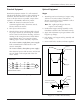
Donaldson Company, Inc. Indoor Exhaust Deflector 1. Remove the top door assembly and set aside. 2. Place a piece of non-combustible cloth over the filters in the clean-air chamber to protect them from drilling chips. 3. Use a .213-in diameter drill bit to drill eight holes as shown. 4. Position the indoor exhaust deflector on the cabinet top and fasten using eight 1/4-20 thread-cutting screws. Tighten securely. 5. Carefully remove the cloth protecting the filters.
Cabinet Dust Collector, Series 50 to 80 Outdoor Exhaust Deflector 1. Remove the top door assembly and set aside. 2. Place a piece of non-combustible cloth over the filters in the clean-air chamber to protect them from drilling chips. 4. Position the indoor exhaust deflector on the cabinet top, align holes and fasten using eight #10-24 x 1/2-in bolts, washers, and nuts supplied. Tighten securely. 3. Use a .218-in diameter drill bit to drill eight holes as shown. 5.
Donaldson Company, Inc. Ductwork Suction Tube Assembly Note: If unit is operated with more than the maximum permissible inlet size, the fan motor can overload or dust can settle in the duct due to low air velocity. 3- and 4-Inch 1. Inlet collars can be located on the side, top, or back of the cabinet by removing the desired inlet cover plate and installing the inlet collar using the same screws. 1. Apply a thin layer of grease to the inside surface of the inlet collar. 2.
Cabinet Dust Collector, Series 50 to 80 6-Inch 1. Remove the inlet access covers on the top and back of the unit and set aside. 4. Position the suction tube assembly on the collector top, align holes, and fasten securely using 5/16-18 x 1 1/4-in bolts, washers, and nuts supplied. 2. Use a .343-in diameter drill bit to drill four holes in the top of the unit as shown. 3. Apply sealant around the inside edge of the bolt pattern. 5. Replace the back access cover plate. 5/16-18 x 1.
Donaldson Company, Inc. Magnehelic Gauge The Magnehelic is a differential pressure gauge used to measure the pressure difference between the clean- and dirty-air chambers and provides a visual display of filter change requirements. The high-pressure tap is located in the dirty-air chamber and the low-pressure tap is located in the clean-air chamber. 1. Choose a convenient, accessible location on or near the unit for mounting that provides the best visual advantage.
Cabinet Dust Collector, Series 50 to 80 6. Mount the gauge and bracket assembly to the supporting structure using two self-drilling screws. 8. Carefully remove the cloth protecting the filters. Close access doors and tighten securely by hand. 9. Zero and maintain the gauge as directed in the manufacturer’s Operating and Maintenance Instructions provided. Series 7. Thirty-five feet of plastic tubing is supplied and must be cut in two sections.
Donaldson Company, Inc. Outrigger Pack Note: Outrigger pack is for use with dust drawer models only. 3. Drill four .312-in diameter holes in the cabinet base using the mounting tab holes as a guide. 1. Center the unit on the outrigger pack aligning the appropriate bolt patterns. 4. Attach the cabinet base to the mounting tabs using four 5/16-18 x 3/4-in bolts, washers, and nuts. Tighten securely. 2. Fasten the four mounting tabs to the outrigger base using four 5/16-18 x 4-in bolts, washers, and nuts.
Cabinet Dust Collector, Series 50 to 80 HEPA Filter Models 60 and 70 1. Position the HEPA filter pack on top of the unit as shown. 6. Remove HEPA filter pack and apply silicone sealant around mounting surface. 2. Remove the top door assembly and set aside. 7. Fasten angle bracket to cabinet using four 1/4-20 thread-cutting screws supplied. 3. Place a piece of non-combustible cloth over the filters in the clean-air chamber to protect them from drilling chips. 4.
Donaldson Company, Inc. Model 80 1. Remove the top door assembly and set aside. 2. Place a piece of non-combustible cloth over the filters in the clean-air chamber to protect them from drilling chips. 3. Use a .312-in diameter drill bit to drill four holes in the collector top as shown. 5. Position the HEPA filter pack on top of the unit aligning holes. 6. From inside the clean-air chamber, fasten the filter pack to the top using four 1/4-20 threadcutting screws. 7.
Cabinet Dust Collector, Series 50 to 80 Exhaust Silencer If an exhaust silencer was ordered with the unit, the mounting holes are pre-drilled. 3. Use a .116-in diameter drill bit to drill eight holes in the collector top as shown. To install an add-on silencer: 4. Position the exhaust silencer, align holes, and fasten securely with #7 x 1/2-in screws supplied. 1. Remove the top door assembly and set aside. 2.
Donaldson Company, Inc. Attenuator If an attenuator was ordered with the unit, the mounting holes are pre-drilled. 3. Use a .213-in diameter drill bit to drill eight holes in the collector top as shown. To install an add-on attenuator: 4. Position the attenuator assembly, align holes, and fasten securely using eight 1/4-20 threadcutting screws supplied. 1. Remove the top door assembly and set aside. 2.
Cabinet Dust Collector, Series 50 to 80 Chamber Silencer Automatic Shaker 1. Place the chamber silencer over the clean-air outlet on top of the unit. The automatic shaker is driven by a 1/10 Hp TENV gear motor controlled by a solid-state timer. The timer control box can be ordered with or without step-down transformers. A timer control box without the transformer requires a 120-Volt AC power supply controlled by a customer-supplied fan starter.
Donaldson Company, Inc. 60-second delay-on-make timer red wire 30-sec interval timer gray wire gray wire fuse MDX 3 amp red wire fan starter normally closed auxiliary control red wire 110-Volt Power Source Series 50 to 80 Automatic Shaker without Transformer interval timer Note: The automatic shaker requires a 120-Volt power supply controlled by the fan starter. The normally-closed auxiliary contact is supplied by others.
Cabinet Dust Collector, Series 50 to 80 transformer specify voltage red wire black wire green wire gray wire 60-second delay-on-make timer black wire 30-sec interval timer gray wire fuse MDX 3 amp gray wire red wire fan starter normally closed auxiliary control red wire Series 50 to 80 Automatic Shaker with Transformer 1L1 1L2 1L3 1M 1OL Electrical Control Box 1FU L1 2FU L2 1T2 3FU L3 1T3 1T1 H1 fan motor X1 230V H3 H2 115V H4 X2 230/460V 60 Hz/3Ph interval timer delay timer 4
Donaldson Company, Inc. Preliminary Start-Up Check Start-Up 1. Check all electrical connections for tightness and contact. 1. Turn power ON at source. 2. Check for and remove all loose items in or near the inlet and outlet of the unit. 2. Turn unit ON. 3. Check that all remote controls are wired into the control system, and all service switches are in the OFF position. 3.
Cabinet Dust Collector, Series 50 to 80 Service Information EZ Filter Pack Installation Step 1 Step 2 B B C D E Step 1 Step 2 A. Remove top and bottom doors and set aside. A. Remove banded EZ Filter Pack from box. Do not remove bands. B. Remove and discard set screws and hold-down channels. C. Remove and discard envelope bags. B. Loosen wing screws fully. C. Move slide latches back, away from the gasket. D. Clean bottom of cabinet ledge with stiff brush.
Donaldson Company, Inc. Step 5 Step 6 Step 5 Step 6 A. Place one hand under the center of the EZ Filter Pack. A. Distribute filter envelopes evenly. B. Finger-tighten wing screws. B. Hold filter back against bottom of cabinet ledge. C. Push each slide latch over cabinet ledge. D. Do not tighten wing screws at this time. Step 7 Step 8 Step 7 Step 8 A. Place support bar over center of EZ Filter Pack. A. Inspect filter seal. B. Insert small wing screws through holes in support bar. B.
Cabinet Dust Collector, Series 50 to 80 EZ Filter Pack Maintenance Dust Disposal 1. Manually or automatically clean the filters once each day depending on load circumstances. 1. Turn unit OFF and empty dust container as necessary to minimize dust in the hopper. 2. A good practice is to clean filters at break, lunch, and end of day. 2. If the optional 5- or 55-gallon drum attachment is used, empty when drum is 2/3 full. 3. If optional slide gate is used, close gate before servicing drum. 4.
Donaldson Company, Inc. Troubleshooting Problem Probable Cause Rem edy Blower fan and motor do not start Improper motor wire size R ewire using the correct wire gauge as specified by national and local codes. Not wired correctly C heck and correct motor wiring for supply voltage. See motor manufacturer's wiring diagram. Follow wiring diagram and the National Electric C ode. U nit not wired for available voltage C orrect wiring for proper supply voltage.
Cabinet Dust Collector, Series 50 to 80 Problem Probable Cause Rem edy Insufficient airflow Fan rotation backwards Proper fan rotation is clockwise when looking down at the blower motor. See Preliminary Start-U p C heck on Page 26. A ccess doors open or not closed tight C heck that all access doors are in place and secured. C heck that the hopper discharge opening is sealed and that optional attachments are installed correctly. See Hopper A ttachments o n P age 11.
Donaldson Company, Inc. Troubleshooting continued Problem Probable Cause Rem edy A utomatic shaker mechanism not working continued Delay-on-make timer C heck input voltage to the delay-on-make timer's Terminal D1. A fter the 60-second delay, check for voltage on Terminal D2. If input voltage is present, but no output voltage, replace the delay-on-make timer. Interval timer A fter the 60-second delay, check for voltage at the interval timer Terminal T1.
Cabinet Dust Collector, Series 50 to 80 Service Notes Date Service Performed Notes 33
The Donaldson Torit Warranty Donaldson Company, Inc. warrants to the original purchaser that for a period of ten (10) years from the date of shipment, the product described herein shall be free from defects in materials and workmanship if properly installed, maintained and operated under normal conditions.