BUSH HOG ® Model 2715 / 2710 Flex-Wing Rotary Cutter Operator’s Manual ASSEMBLY l OPERATION l MAINTENANCE 06/09 Rev. 1 $4.
CONGRATULATIONS! You have invested in the best implement of its type on the market today. The care you give your Bush Hog implement will greatly determine your satisfaction with its performance and its service life. We urge a careful study of this manual to provide you with a thorough understanding of your new implement before operating, as well as suggestions for operation and maintenance. If your manual should become lost or destroyed, Bush Hog will be glad to provide you with a new copy.
2715 ROTARY CUTTER TABLE OF CONTENTS SECTION/PARA PAGE Warranty ................................................2 Dealer Preparation Check List ...............3 Safety Precautions.................................4 Federal Laws and Regulations ..............5 I. INTRODUCTION & DESCRIPTION ......6 1-1 Introduction ......................................6 1-2 Description.......................................6 Key Operation Points .............................8 II. PREPARATION FOR USE ....................
LIMITED WARRANTY OOOOOOOOOOOOOOOOOOOOOOOOOOOOOOO Bush Hog warrants to the original purchaser of any new Bush Hog equipment, purchased from an authorized Bush Hog dealer, that the equipment be free from defects in material and workmanship for a period of one (1) year for non-commercial, state and municipalities’ use and ninety (90) days for commercial use from date of retail sale. Model 2715 / 2710 gearboxes are covered by a five (5) year limited warranty period.
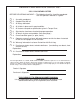
DEALER PREPARATION CHECK LIST 2715 / 2710 ROTARY CUTTER BEFORE DELIVERING MACHINE — The following check list should be completed. Use the Operator’s Manual as a guide. r r r r r r r r r 1. Assembly completed. 2. Gearbox filled with oil. 3. All fittings lubricated. 4. All shields in place and in good condition. 5. All fasteners torqued to specifications given in Torque Chart. 6. Slip clutches have been checked for proper operation. 7. All decals in place and readable. (See decal page.) 8.
IMPORTANT SAFETY PRECAUTIONS This symbol is used to call attention to safety precautions that should be followed by the operator to avoid accidents. When you see this symbol, carefully read the message that follows and heed its advice. Failure to comply with safety precautions could result in serious bodily injury.
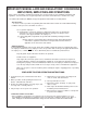
IMPORTANT FEDERAL LAWS AND REGULATIONS* CONCERNING EMPLOYERS, EMPLOYEES AND OPERATIONS. *(This section is intended to explain in broad terms the concept and effect of the following federal laws and regulations. It is not intended as a legal interpretation of the laws and should not be considered as such). U.S. Public Law 91-596 (The Williams-Steiger Occupational and Health Act of 1970) OSHA This Act Seeks: “...
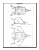
SECTION I INTRODUCTION AND DESCRIPTION Height Adjustment Cylinder Center Blade Gearbox Figure 1-1 Power Divider Gearbox (Under Shield) Tongue Height Adjustment Axle Laminated Tire Hose Holder Rod C.V Driveline Wing Transport Lock Tongue Jackstand Discharge Shield (Chains) 1-1 INTRODUCTION Driveline Retainer Wing Blade Gearbox Replaceable Wing Skid Power from the tractor PTO is split at the power divider gearbox and supplied to each of the blade gearboxes.
2715 Dimensions 195” 94” 109” 86” 191” 195” 7
• • KEY OPERATION POINTS Cutting performance and distribution are best when cutter is level from side to side and front to rear. In extra heavy material, rear chains will allow better discharge and better distribution than solid rear bands. • • • • • • • Never operate the Flexwing below full PTO speed of 540 or 1000 rpm. For good distribution, the distribution baffles must be used. Deck rings may influence the quality of distribution.
SECTION II PREPARATION FOR USE 2-1 ATTACHING TO TRACTOR WARNING USE A PIECE OF CARDBOARD OR WOOD RATHER THAN HANDS AND WEAR EYE PROTECTION WHEN SEARCHING FOR HYDRAULIC LEAKS. ESCAPING HYDRAULIC OIL UNDER PRESSURE CAN PENETRATE SKIN. IF OIL IS INJECTED INTO SKIN, IT MUST BE SURGICALLY REMOVED WITHIN A FEW HOURS BY A DOCTOR OR GANGRENE MAY RESULT. A. IMPORTANT - Adjust tractor drawbar length to dimension shown in Figure 2-1.
C. Attach valve to top bracket using three 3/8” x 21/2” bolts, nuts and lockwashers. D. Mount top bracket to bottom bracket using quarter turn fasteners. Insert quarter turn fastener into clip-on receptacle and turn 90 degrees. 2-2 OPTIONAL VALVE MOUNTING BRACKET INSTALLATION (Figure 23) A. Place bottom bracket at desired mounting location. Mark 2-4 holes (as needed) for drilling using bracket as pattern. Drill holes using 13/32 drill bit. B.
If you are cutting in dense material, operating cutter with the rear slightly higher than the front will allow an increased volume of cut material to exit from underneath cutter. This will decrease the cutter horsepower requirements. CAUTION FAILURE TO MATCH VALVE TO TRACTOR HYDRAULIC SYSTEM BY USING INCORRECT PLUG WILL CAUSE DAMAGE TO TRACTOR.
Adjust the pitch as follows: A. Loosen jam nut on each linkage rod assembly. (Figure 2-3). B. Use the turnbuckles to lengthen or shorten the leveling rod assemblies. Shortening the rods will raise the front of the cutter and lengthening rods will lower the front of the cutter. While adjusting, alternate from one rod to the other. C. When the desired pitch is attained, make a final adjustment of the rods so that each will be under the same amount of tension.
A. Disengage tractor PTO. B. Raise cutter and install stop collars on height adjustment cylinder. Install transport lock. C. Raise wing(s) and insert transport lock pin(s). DANGER ROTARY CUTTER BLADES. STAND WELL CLEAR UNTIL ALL MOTION HAS STOPPED. TO AVOID AN ACCIDENTAL FALL FROM TRACTOR AND POSSIBLE INJURY OR DEATH BY MOWER, IT IS RECOMMENDED THAT TRACTOR BE EQUIPPED WITH ROLLOVER PROTECTIVE SYSTEM (ROPS) AND A SEAT BELT BE USED BY THE OPERATOR FOR ALL MOWING OPERATIONS. 3-3 OPERATION A.
include the components current safety decals specified by the manufacturer to be affixed to the component. 3. Store cutter in a dry place. WARNING THE CUTTER CAN FALL FROM HYDRAULIC SYSTEM FAILURE. TO AVOID SERIOUS INJURY OR DEATH, SECURELY SUPPORT CUTTER BEFORE WORKING UNDERNEATH. 4-2 LUBRICATION (Figure 4-1) BEFORE EACH USE 1. Make certain driveline shields are in place and in good repair to minimize entanglement injuries to persons by rotating drivelines.
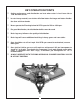
Bondioli & Pavesi Drivelines 3 1 Input CV Driveline 1 Comer Drivelines 3 1 1 1 Input CV Driveline 2 2 2 Center Shaft 2 1 1 1 1 2 Wing Driveline 1 1 2 Center Shaft 2 1 1 1 5 5 Wing Driveline 1 5 1 5 1 2 2 2 Walterscheid Drivelines 1 Input Driveline 5 Figure 4-1 Lubrication Jackshaft 1 (7) Before Each Use (6) Before Each Use (4) Before Each Use (8) 40 Hrs. (4) Before Each Use (9) 120 Hrs.
BUSH HOG ® MODEL 2715/2710 FLEX-WING ROTARY CUTTER (Model 2710 Illustrated) 16
17
To Remove Yoke Shield From Bondioli & Pavesi Driveline: Remove the four screw fromthe rear side of the shield and slide shield away from U-joint. To Remove Yoke Shield From EG/Comer Driveline: Using a screwdriver, turn the plastic head 90° counterclockwise and slide shield away from U-joint. Plastic Head Shield Removal Screws Shield Removal Screws C. Assemble new blades to blade holder using blade bolts, nuts and lockwashers. Refer to BLADE ROTATION DIAGRAM for blade placement.
turn increments. Adjust only to provide sufficient torque to prevent slippage under normal conditions. Occasional slippage is normal for drivetrain protection. If satisfactory results cannot be obtained consult your Bush Hog dealer. 4-4 SLIP CLUTCH OPERATIONAL CHECK After implement has been stored for 30 days or more, perform the following operational check: A. Loosen eight nuts retaining clutch springs 1/3 turn or until spring can be turned with fingers. B.
SECTION V ASSEMBLY CAUTION THE FOLLOWING SAFETY PRECAUTIONS SHOULD BE THOROUGHLY UNDERSTOOD BEFORE ATTEMPTING MACHINE ASSEMBLY. 1. Wear personal protective equipment such as, but not limited to protection for eyes, ears, feet, hands, lungs and head when assembling the equipment. Do not wear loose clothing or jewelry that may catch on equipment moving parts. 2. Do not lift heavy parts or assemblies. Use crane, jack, tackle, fork trucks or other mechanical devices. 3.
Figure 5-2 Axle Cylinder Mounting Holes Automotive And Large Aircraft Tires E .If the wing sections are equipped with single wheel option, the wheel should be assembled to the outside of the axle arms. F. Bolt tongue to center section using two 1” x 8-1/2” bolts, locknuts and bushings. G. Fasten linkage rods to the holes in the tongue side plates using 1” x 5” pins, two 1” flatwashers and roll pins. H. Attach turnbuckle end of linkage rods to axle using pins and cotter pins.
M. Place a 2-4 inch block under each center section front skid. Raise rear of center section until it is level and install stop collars on height adjustment cylinder to retain in this position. M-1. Install Nord Lockwasher (Two Piece) on turnbuckle by loosening the jam nut on the threaded end and removing the rod end from the turnbuckle.
O. Install wing over center stops on each wing lug using 3/8 x 1” bolts and lock washers. Install wing lift cylinders with rod end connected to the wing lug. It may be necessary to remove port plugs to extend cylinder. Install the cylinder in the slotted holes. Place a 1-1/4” diameter x 1” long cylinder pin spacer bushing between the ears of the cylinder. Secure cylinder in slot with 53/8” pin, flatwashers and cotter pins.
AA. Fill each gearbox with six quarts (5.7L) of EP80W-90 gearbox oil. Allow time for oil to seep through bearings into lower housing. Replace temporary plugs with permanent plugs supplied in owner’s manual package. BB. On each clutch, loosen eight nuts retaining clutch springs 1/3 turn or until spring can be turned with fingers. CC. With tractor at idle speed, engage tractor PTO drive 2-3 seconds. Each clutch should slip without turning blades. DD. Retighten nuts to within 1/64” of original position.
and fasten with cotter pins on each end. F. Position connector through the pivot tube using a 1” nut on each side. Leave nuts slightly loose until final positioning. G. Place the clevis end of the connector over the lugs on the center section and fasten with 7/8” locknut. Repeat on opposide end of the weight box. Adjust each connector equally so that the weight box extends straight down and there is 1” clearance between the box and the center section.
5-4 BAND INSTALLATION A. Compare each piece of belting and supports to Figure 5-20 to determine location for installation. B. Place belting between two supports. Align holes in belt and support with those on cutter. Insert carriage bolts through deck, supports and belting. Secure with lockwashers and nuts. (Figure 5-22) C. Tighten all nuts. A. Raise wings to the transport position and install transport lock pins.
Center Section Baffle Hinge Tube 27 1/2” x 1-1/2” 1/2” x 1-1/2” Right Wing Baffle Left Wing Baffle 3/8” x 1-1/2” 1/2” x 1-1/2” 1/2” x 1-1/2” Left Center Baffle 1/2” x 1-1/2” 1/2” x 1-1/2” Note the bend angle of the center baffle extensions. The sides are interchangeable.
228” Hydraulic Hose 2715 PLUMBING DIAGRAM (USING REMOTE VALVE) 228” Hydraulic Hose 90° Elbow 3/4” SAE “O” Ring Boss to 9/16” JIC Breather Plug Center Height Control Cylinder 28 228” Hydraulic Hose
Breather Plug 29 228” Hydraulic Hose 90° Elbow 3/4” SAE “O” Ring Boss to 9/16” JIC Breather Plug IMPORTANT DURING OPERATION THE HYDRAULIC VALVE WING LEVERS MUST BE LOCKED IN THE FLOAT POSITION TO AVOID DAMAGE TO THE CYLINDERS AND AXLES.
SAFETY DECALS To promote safe operation, Bush Hog supplies safety decals on all products manufactured. Because damage can occur to safety decals either through shipment, use or reconditioning, Bush Hog will, upon request, provide safety decals for any of our products in the field at no charge. Contact your authorized Bush Hog dealer for more information.
78786 50029418 78608 31
TORQUE SPECIFICATIONS Proper toque for American fasteners used on Bush Hog equipment. Recommended Torque in Foot Pounds (Newton Meters).* AMERICAN Bolt Head Markings SAE Grade 2 (No Dashes) SAE Grade 5 (3 Dashes) lt ” Bo r “B te e m Dia Wrench Size “A” SAE Grade 8 (6 Dashes) METRIC WRENCH SIZE (IN.) “A” BOLT DIAMETER (IN.
2501 Griffin Ave. l Selma, AL 36703 Telephone (334) 874-2700 l www.bushhog.