® BUSH HOG BACKHOES Operator’s Manual MODELS 665H / 765H / 865H / 965H ASSEMBLY • OPERATION • MAINTENANCE 801 $4.
CONGRATULATIONS! You have invested in the best implement of its type on the market today. The care you give your Bush Hog implement will greatly determine your satisfaction with its performance and its service life. We urge a careful study of this manual to provide you with a thorough understanding of your new implement before operating, as well as suggestions for operation and maintenance. If your manual should become lost or destroyed, Bush Hog will be glad to provide you with a new copy.
BACKHOES Operator’s Manual TABLE OF CONTENTS SECTION/PARA SECTION/PARA PAGE PAGE Beginning of Season .................................14 Hydraulic System ......................................14 Lubrication ................................................ 15 Removal/Storage....................................... 16 Stabilizer Pads ..........................................17 Hydraulic Trouble Shooting........................17 Valve Repair...............................................19 Assembly.......
BUSH HOG® LIMITED WARRANTY ✯✯✯✯✯✯✯✯✯✯✯✯✯✯✯✯✯✯✯✯✯✯✯✯✯✯✯✯✯✯✯ Bush Hog warrants to the original purchaser of any new Bush Hog equipment, purchased from an authorized Bush Hog dealer, that the equipment be free from defects in material and workmanship for a period of one (1) year for non-commercial, state, and municipalities’ use and ninety (90) days for commercial use from date of retail sale.
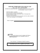
DEALER PREPARATION CHECK LIST 665H - 765H - 865H - 965H BACKHOES BEFORE DELIVERING MACHINE - The following check list should be completed. Use the Operator’s Manual as a guide. ❑ ❑ ❑ ❑ ❑ Machine properly assembled. All safety decals readable (See decal page). All bolts tightened to torque specifications given in the torque chart. Machine operates properly. Operators manual has been delivered to owner and he has been instructed on the safe and proper use of the backhoe.
IMPORTANT SAFETY PRECAUTIONS This symbol is used to call attention to safety precautions that should be followed by the operator to avoid accidents. When you see this symbol, carefully read the message that follows and heed its advice. Failure to comply with safety precautions could result in serious bodily injury.
SAFETY PRECAUTIONS CONTINUED 12. DO NOT dig under stabilizers or tractor backhoe. Soft ground or sandy soil can cause cave-ins. 13. KEEP BUCKET away from the stabilizer area to avoid possible stabilizer damage. 14. ALWAYS swing bucket uphill to dump when on a hillside and keep loaded bucket low. 15. SET BRAKES and block wheels when operating on hills and banks to avoid dangerous runaway. 16. WATCH for overhead wires. DO NOT touch wires with any part of the backhoe. 17.
SAFETY DECALS The safety of the operator was a prime consideration in the design of the backhoe. Proper shielding, convenient controls, simple adjustments and other safety features have been built into this implement. The following decals are located on the backhoe. Keep decals clean and replace them immediately if they are missing. Contact your dealer or Bush Hog for replacements.
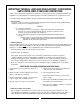
IMPORTANT FEDERAL LAWS AND REGULATIONS* CONCERNING EMPLOYERS, EMPLOYEES AND OPERATIONS. *(This section is intended to explain in broad terms the concept and effect of the following federal laws and regulations. It is not intended as a legal interpretation of the laws and should not be considered as such). U.S. Public Law 91-596 (The Williams-Steiger Occupational and Health Act of 1970) OSHA This Act Seeks: “...
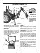
GENERAL OPERATION Figure 1 Dipper-Stick Safety Swing Lock Position Boom Boom Safety Lock Position Mainframe CAUTION To avoid the possible Bucket injury, observe the following safety rules BEFORE Link OPERATING the backhoe: 1. BE SURE area is clear of underground utilities or other hazards. 2. POSITION barricade around work area. 3. PROVIDE adequate front end weight to counter-balance tractor at all times. 20% of the total tractor, loader and backhoe weight must be on the tractor front axle. Bucket 4.
Figure 3 Safety Locks Swing Safety Lock Boom Safety Lock SWING RIGHT AND LOWER the boom by moving the lever forward and to the right. ations from the two levers, keeping cycle time to a minimum. SWING RIGHT AND RAISE the boom by moving the lever back and to the right. In general, the direction of movement of a control lever corresponds to the movement of the operating member. 2. Left Hand Stabilizer: Push lever forward, the LH stabilizer lowers. Pull lever back, the LH stabilizer raises.
Location: Back Of Control Panel It is not difficult to become an efficient operator. Control lever operating decal is located on back of the control panel. Study this decal. It will assist you in becoming familiar with the controls. This dual operation of controls will speed and simplify the digging operation.
4. USE accessory lights and SMV emblem when traveling on highways. CAUTION To avoid possible injury, observe the following safety rules when transporting the backhoe: Before leaving backhoe operator’s seat, position the backhoe for transport by raising boom, crowding dipperstick in, swinging to center and raising the stabilizers. 1. ALWAYS engage safety locks as shown on Figs. 1 and 3 when transporting backhoe. 2. TRAVEL SLOWLY over rough terrain, on hillsides, and around curves to prevent tipping.
General Operations As the pile is approached, dump the bucket. When the bucket is empty, the dipperstick and bucket are in position to resume digging upon return to the trench. IMPORTANT: Avoid constant jarring or hammering-type contact between the spoil pile and the loaded bucket, as this may cause premature wear to the backhoe pins and bushings. FILLING THE BUCKET Control the bucket attitude throughout the digging cycle to keep teeth at the proper angle for best penetration.
General Operations MISCELLANEOUS When finishing straight walls or bellholes in sandy soil, use a platform under the rear tires and the stabilizers. The platform distributes the load over a larger area and lessons the possibility of a cave-in. The platform also tends to keep the unit from creeping rearward if hard digging is encountered. SIDE SLOPE EXCAVATING OR TRENCHING Dig with the backhoe uphill whenever possible.
SERVICE CAUTION To avoid possible injury, observe the following safety rules WHEN SERVICING the backhoe: placing the unit under full load. 1. ENGAGE safety locks as shown in Figures 1 & 3 before servicing the backhoe. If the hydraulic hoses have been disconnected from the backhoe or tractor, all trapped air must be removed after the hoses are connected. Start tractor engine and operate backhoe through all movements fully, several times, to purge the system of air. Bleeding Backhoe Hydraulic System 2.
Tooth Replacement The bucket tooth points are self-sharpening and will require little attention; however, these points on the bucket shanks can be replaced when they become badly worn or broken. If a tooth shank breaks off, becomes damaged or lost so that it cannot hold a tooth point, a new shank should be welded to the bucket in its place.
REMOVAL FROM TRACTOR - STORAGE Figure 9 Backhoe Shown Partially Extended Backhoe Fully Extended Blocking For Support CAUTION The backhoe is self-assisting during the installation and removal procedures. For removal and storage, follow these steps: Make sure tractor PTO is disengaged and engine shut off before disconnecting pump or hydraulic lines. a. On PTO pump self-contained systems the pump should be removed from the PTO shaft. The hydraulic system should always remain complete.
Stabilizer Pads - 765H, 865H and 965H Problems and Possible Causes, Continued The backhoe is supplied with flip-over stabilizer pads as standard equipment. They are suitable for most backhoe work and generally are all that is ever required. However, street pad kits are available as options for Models 765H, 865H and 965H backhoes. These kits bolt to the standard pads and increase the versatility of the backhoe. See Figure 10. D.
27. Check poppet in the control valve not holding clean check poppet(s) carefully, being sure that it moves freely with good spring action and seats properly or replace. See item 30 at the end. Causes and Corrections, Continued 12. Bent piston rod in cylinder - replace or rebuild the cylinder; replace damaged parts. 13. Worn or damaged rod seals on cylinder; external leaks - repack cylinder. Rebuild cylinder, replacing damaged parts as necessary. 14.
VALVE REPAIR - DISASSEMBLY Figure 11 SCREW 5/16-18 x 3/4 RETURN SPRING RETAINER SPOOL COLLAR RETURN SPRING BACK-UP WASHER SPRING COLLAR SCREW, 5/16-18 x 3/4 SPOOL COLLAR LOCKWASHER LOCKWASHER SPRING COLLAR O-RING SEAL SCREW, 1/4-20 x 7/8 STANDARD SPRING CENTERED BONNET ASSEMBLY RETURN SPRING DETENT BALL FOLLOWER BONNET U-CUP SEAL FLOAT SLEEVE RETAINING SLEEVE RETAINING RING STOP COLLAR DETENT SPRING DETENT BALL O-RING SEAL SCREW, 1/4-20 x 7/8 LOCKWASHER FLOAT BONNET ASSEMBLY 7.
1. Remove control valve from the backhoe. valve spool and insert in seal counterbore. Replace back-up washer and seal retainer. 2. Thoroughly clean the exterior of the valve before beginning disassembly procedures. B. Float Bonnet Assembly Only: 3. At the BACK of the valve remove all bonnet assembly parts which are connected to the spool. Keep parts in the order of disassembly. See Figure 11 for the parts involved in the make-up of the bonnet assembly. Replace retaining sleeve on valve spool.
3. Remove plastic bag containing bucket pins from backhoe. Attach bucket (D) to dipperstick using one pin, two bolts, nuts, lockwashers, pin retainers and washers as necessary. 6. Attach stabilizer cylinders (H) to stabilizers using pins and hardware assembled to stabilizers. 4. Attach bucket link (E) to bucket, using same hardware as listed for step #3. 7. Using caution to prevent tipping, raise mainframe with hoist to a height of approximately 11” for 862H and 13” for 962H and remove skid.
using 3/4 x 4-1/2” bolt (9), flat washers (10), lockwasher (9) and nut (11). Use hoist to raise or lower backhoe slightly until a hole in the upper bar aligns with a hole in the upper braces. See Figure 13. ASSEMBLY (Refer to Figures 13 & 14) IMPORTANT: Tighten all hardware to the torque requirements specified in the torque chart. WARNING 6. Attach RH lower link weldment (1) and LH lower link weldment (2) to backhoe mainframe using 3/4 x 2-1/4” bolt (15), flat wahser (10), lockwasher (9), and nut (11).
Figure 14 (665H & 765H) 11 9 10 14 7 8 10 20 12 13 19 16 7 10 9 11 1 10 11 18 10 17 9 9 2 10 15 6 5 3 4 ATTACHING KIT INSTRUCTIONS (For 865H) 3-POINT HITCH LINKAGE & HYDRAULIC HOOK-UP TO TRACTOR HYDRAULIC SYSTEMS General Description link to the backhoe mainframe, locking the hoe rigidly in one position. Mounting and hydraulic kits include two hoses which can be used in connecting the backhoe control valve to the tractor hydraulic system.
Figure 15 14 12 11 7 9 10 13 26 24 16 17 25 8 22 28 29 15 23 27 36 35 25 25 3 37 24 33 26 22 35 30 24 6 38 32 1 25 34 25 26 25 2 31 21 4 5 20 19 ASSEMBLY 18 5. Back tractor close to the backhoe. Connect tractor lower link arms to lower link mounts at position “C”, Figure 16, using two L-pins (18), two cotter pins (19), and two wire form cotter pins (20) as shown in Figure 15. IMPORTANT: Tighten all hardware to the torque requirements specified in the torque chart.
Figure 16 Upper Bar Tractor Upper Link Bracket Upper Brace Link Weldment Backhoe Mainframe Tractor Lower Link C correctly installed and securely fastened. 10. Align RH and LH link weldment (12) with a hole in the upper bar/brace assembly, as close to the tractor as possible. Use 3/4 x 6” bolt (32), flat washer (25), lockwasher (24), and nut (26). See Figure 15. You may need to return to Step 6 and readjust upward or downward the bolt connection. 14.
Note: Do not connect hoses from the backhoe control valve to the tractor hydraulic system until initial assembly of mounting kit is complete. Note: The surge relief valve is not supplied with the backhoe or mounting kit and must be ordered separately to complete this type hydraulic hook-up. 1.
is completely destroked and there is no delivery. Hydraulic Hook-Up (865H & 965H) For Tractors With Closed-Center Hydraulic Systems Therefore, when working various backhoe functions at near maximum ability, it will give the operator the impression that the backhoe is sluggish and somewhat unresponsive. Learning to ease up slightly at the first indication of slow down will permit the backhoe to perform at continuing maximum speed and efficiency.
Figure 21 (965H) 207 217 213 207 210 220 221 216 210 210 203 206 205 208 200 204 210 219 210 209 207 203 207 218 210 210 202 215 214 212 211 ATTACHING KIT INSTRUCTIONS (For 965H) 3-POINT HITCH LINKAGE & HYDRAULIC HOOK-UP TO TRACTOR HYDRAULIC SYSTEMS General Description link to the backhoe mainframe, locking the hoe rigidly in one position. Mounting and hydraulic kits include two hoses which can be used in connecting the backhoe control valve to the tractor hydraulic system.
ASSEMBLY (Refer to Figure 21 & 22) IMPORTANT: Tighten all hardware to the torque requirements specified in the torque chart. WARNING TO PREVENT BODILY INJURY, DO NOT OPERATE BACKHOE UNLESS LOWER LINK WELDMENTS (217,218) ARE PROPERLY INSTEALLED AND ADJUSTED. FAILURE TO DO SO MAY RESULT IN BACKHOE BEING THRUST UPWARD, CRUSHING OPERATOR AGAINST CAB OR ROPS. 1. Use hoist to raise the backhoe mainframe so that the boom pivot pin is approximately 16” off the ground. 2. Back tractor close to the backhoe.
TORQUE VALUES Common bolts and nuts Size Grade 2 Tightening Torque Plus/Minus 20% Grade 5 Grade 8 1/4-20 NC 1/4-28 NF 70 in. lbs. 85 in. lbs. 115 in. lbs. 140 in. lbs. 165 in. lbs. 200 in. lbs. 5/16-18 NC 5/16-24 NF 150 in. lbs. 165 in. lbs. 250 in. lbs. 270 in. lbs. 350 in. lbs. 30 ft. lbs. 3/8-16 NC 3/8-24 NF 260 in. lbs. 300 in. lbs. 35 ft. lbs. 40 ft. lbs. 50 ft. lbs. 60 ft. lbs. 7/16-14 NC 7/16-20 NF 35 ft. lbs. 45 ft. lbs. 55 ft. lbs. 75 ft. lbs. 80 ft. lbs. 105 ft. lbs.
obtained from Bush Hog Service Parts. Before attempting to order the plug you must first determine the manufacturer of the loader valve assembled to your loader. This can be determined from the identification plate located on the valve. ASSEMBLY OF A BUSH HOG BACKHOE TO A BUSH HOG LOADER VALVE IMPORTANT: Improper hydraulic hook-up can cause serious damage to backhoe control valve or other hydraulic components. Refer to the Bush Hog loader Operator’s Manual during this procedure. 1.
BUSH HOG BACKHOE & BUSH HOG LOADER VALVE FIGURE 23 NOTE: Large loader valve shown. Small loader valve porting is different. Refer to loader operator’s manual for different valves. Outlet Inlet Bush Hog Loader Valve Open Center Plug Power Beyond Plug (Supplied With Valve) Backhoe Tractor Pressure Outlet Outlet Plug Inlet Return Line Pipe Tee Tractor Reservoir Port IMPORTANT: Never connect the return hose to a tractor remote coupler which can be pressurised.
865H & 965H - Assemble straight O-ring adapter union (3) to power beyond sleeve (1). Install 90 degree pipe threaded adapter union (2) into adapter union (3). ASSEMBLY: BUSH HOG BACKHOE AND A NON BUSH HOG LOADER - OR - BUSH HOG BACKHOE AND LOADER USING PTO PUMP KIT OPTION 3. Assemble hydraulic hose (supplied by customer) to adapter union (2) as shown in Figure 24. Hose should have same pressure rating as original pressure hose to loader or other accessory valve.
Figure 24 1 3 OUTLET 2 4 INLET PRESSURE TO BACKHOE VALVE 8 RETURN FROM BACKHOE VALVE TRACTOR PRESSURE “OUT” PORT PRESSURE TO LOADER VALVE INLET LOADER VALVE OUTLET TEE FITTING RETURN FROM LOADER VALVE TRACTOR RESERVOIR PORT 3 2 2 662H & 762H BACKHOES 862H & 962H BACKHOES 34
PTO PUMP AND RESERVOIR KIT (Optional) er (14), 90 degree beaded fitting (20), and hose clamp (24) as shown in Figure 25. General Description The PTO Pump Kit consists of those parts required to power the backhoe from the tractor’s PTO shaft. It includes the PTO pump and adapter, reservoir, filtration system, hydraulic hoses and fittings. In addition, it includes a pump plate which attaches to the tractor’s draw bar and keeps the pump from turning with the PTO shaft. 6.
PUMP PLATE POSITIONS Figure 25 Pump Plate Pointing Up 4.5 GPM PUMP KIT 18 Pump Plate Pointing Down 19 3 16 28 12 14 6 20 26 22 11 FILTER ONLY FROM BACKHOE “RETURN” 21 24 17 5 9 2 9 2 4 7 24 25 13 23 15 10 27 TO BACKHOE “PRESSURE” 1 Figure 26 6.
BACKHOES - DIMENSIONS AND SPECIFICATIONS SERIES 665H 765H 865H 965H Maximum Digging Depth 7’0” 8’0” 9’0” 10’1” A. Digging Depth (two foot flat bottom) 6’6” 7’6” 8’6” 9’7” B. Swing Arc 180° 180° 180° 180° C. Loading Height (bucket at 60°) 5’0” 5’10” 6’10” 7’8” D. Reach from Center Line of Swing Pivot 8’6” 9’6” 11’1” 12’5” E. Transport Height (maximum) 4’11” 5’9” 6’9” 7’10” F. Bucket Rotation 180° 180° 180° 180° G.
REPOSITION STABILIZER CYLINDERS BEFORE REMOVING BACKHOE FROM SHIPPING PALLET Cylinder ports must be pointing upward and hoses routed above the cylinder to mainframe pivot pin connection.
NOTICE: INSTRUCTIONS FOR MOUNTING BUSH HOG BACKHOES ON SKID STEER LOADERS COME WITH THE INDIVIDUAL MOUNTING KITS. THE EXAMPLE SHOWN BELOW IS A MODEL 865H MOUNTED ON A JOHN DEERE MACHINE.
® BUSH HOG , L.L.C. P.O. Box 1039 ● Selma, AL 36702-1039 Telephone (334) 874-2700 ● www.bushhog.