BUSH HOG ® 2426, 2446, 2846 & 3226QT Front End Loaders Operator’s Manual ASSEMBLY l OPERATION l MAINTENANCE 707 $4.
CONGRATULATIONS! You have invested in the best implement of its type on the market today. The care you give your Bush Hog implement will greatly determine your satisfaction with its performance and its service life. We urge a careful study of this manual to provide you with a thorough understanding of your new implement before operating, as well as suggestions for operation and maintenance. If your manual should become lost or destroyed, Bush Hog will be glad to provide you with a new copy.
2426, 2446, 2846 & 3226 QT TABLE OF CONTENTS SECTION/PARA I SECTION/PARA PAGE Warranty .....................................................3 Dealer Preparation Check List ....................4 Safety Precautions......................................5 Federal Laws & Regulations .......................7 INTRODUCTION & DESCRIPTION ...........8 1-1 Introduction ...........................................8 1-2 Description............................................8 PAGE IV MAINTENANCE ...................
LIMITED WARRANTY OOOOOOOOOOOOOOOOOOOOOOOOOOOOOOO Bush Hog warrants to the original purchaser of any new Bush Hog equipment, purchased from an authorized Bush Hog dealer, that the equipment be free from defects in material and workmanship for a period of one (1) year for non-commercial, state, and municipalities’ use and ninety (90) days for commercial use from date of retail sale. The obligation of Bush Hog to the purchaser under this warranty is limited to the repair or replacement of defective parts.
DEALER PREPARATION CHECK LIST 2426, 2446, 2846 & 3226 QT LOADERS BEFORE DELIVERING MACHINE - The following check list should be completed. Use the Operator’s Manual as a guide. o Machine properly assembled. o All safety decals readable. (See decal page) o All bolts tightened to torque specifications given in torque chart. o Machine operates properly. o Customer has appropriate mounting kit for his tractor and loader. o Customer has appropriate attachments for loader operations.
IMPORTANT SAFETY PRECAUTIONS This symbol is used to call attention to safety precautions that should be followed by the operator to avoid accidents. When you see this symbol, carefully read the message that follows and heed its advice. Failure to comply with safety precautions could result in serious bodily injury.
SAFETY PRECAUTIONS CONTINUED 10. Before disconnecting hydraulic lines, relieve all hydraulic pressure. 11. Do not tamper with the relief valve setting. The relief valve is pre-set at the factory. Changing the setting can cause overloading the loader and tractor and serious operator injury may result. 12. Always wear safety goggles when repairing or servicing machine. 13. When servicing or replacing pins in cylinder ends, buckets, etc., always use a brass drift and hammer.
IMPORTANT FEDERAL LAWS AND REGULATIONS* CONCERNING EMPLOYERS, EMPLOYEES AND OPERATIONS. *(This section is intended to explain in broad terms the concept and effect of the following federal laws and regulations. It is not intended as a legal interpretation of the laws and should not be considered as such). U.S. Public Law 91-596 (The Williams-Steiger Occupational and Health Act of 1970) OSHA This Act Seeks: “...
SECTION I INTRODUCTION AND DESCRIPTION Figure 1-1 Major Components Hydraulic Hoses Mainframe Boom Subframe Boom Cylinder Level Indicator Bucket Cylinder Cross Tube Parking Stands Bucket 1-1 INTRODUCTION 1-2 DESCRIPTION We are pleased to have you as a Bush Hog customer. Your Front End Loader has been carefully designed to give maximum service with minimum down time.
Table 1-1 TECHNICAL SPECIFICATIONS VV U V D E XX A B J C X W G ZZ F Y H SERIES LOADER 2426QT 2446QT 2846QT 3226QT A. Maximum Lift Height - Measured at Pivot Pin 117 in. 117 in. 137 in. 143 in. B. Maximum Lift Height - Under Level Bucket 108 in. 108 in. 128 in. 134 in. C. Clearance with Attachment Dumped 45° 89 in. 89 in. 109 in. 115 in. D. Reach at Maximum Height 26 in. 31 in. 28 in. 28 in. E. Maximum Dump Angle 50° 50° 50° 50° 62 in. 65 in. 76 in. 73 in.
SECTION II LOADER MOUNTING AND DISMOUNTING 2-1 PREPARING TRACTOR Figure 2-1 CAUTION TRACTORS THAT HAVE MOVABLE AXLES MUST BE SET FORWARD IN THE LONG WHEELBASE POSITION AS SHOWN IN FIGURE 2-1 TO PREVENT EXCESSIVE LEVERAGE BEING EXERTED ON THE TRACTOR FRAME. FAILURE TO DO SO CAN RESULT IN PERSONAL INJURY AND EQUIPMENT DAMAGE. REFER TO TRACTOR OPERATOR’S MANUAL FOR ABOVE PROCEDURES AND SPECIFICATIONS FOR YOUR TRACTOR. Short Wheelbase A.
Figure 2-4 Cuff Arrangement WARNING LOADER MODELS: 2426 QT, 3226 QT USE CAUTION WHEN MOUNTING LOADERS EQUIPPED WITH OPTIONAL CONTROL VALVE ON TRACTORS EQUIPPED WITH CANOPY. RAISING LOADER SUBFRAME TOO HIGH CAN PINCH HAND BETWEEN CONTROL HANDLE AND CANOPY CAUSING INJURY. Tighten Nut To 100 ft./lbs. Cuff With Welded-On Bolt D. With tractor at idle speed, carefully activate boom cylinders to raise/lower cross tube until it aligns with front bracket channel. E.
Cylinder Mounting Bushing Figure 2-6 J. Secure hydraulic hoses to tractor to prevent interference. It is recommended that hoses be routed under tractor operator’s platform. K. Extend and retract both sets of cylinders beginning with short strokes. Gradually increase the length of stroke until cylinders “bottom out” in each direction. Hold valve open with cylinders “bottomed out” for 3-5 seconds. This will purge air from hydraulic components.
C. Lower boom until parking stands contact ground. D. Extend bucket cylinders until cutting edge of bucket is frimly on the ground. E. Remove pin from mounting bracket. Pin Figure 2-8 Mounting Bracket G. With tractor at idle speed, roll bucket back until subframe raises up off rear bracket. H. With tractor at idle speed, carefully activate boom cylinder until cross tube is free of pressure within front bracket channel.
FILLING THE BUCKET Approach and enter the pile with a level bucket. ...a level bucket throughout the lifting cycle resists bucket lift and increases breakaway effort. NOTE; Do not be concerned if the bucket is not completely filled during each pass. Maximum productivity is determined by the amount of material loaded in a given period of time. Time is lost if two or more attempts are made to fill the bucket on each pass.
CARRYING THE LOAD DUMPING THE BUCKET Position the bucket as low as possible below the level of the tractor hood for maximum stability and visibility, whether the bucket is loaded or empty. Lift the bucket high enough to clear the side of the vehicle. Move the tractor in as close to the side of the vehicle as possible, then dump the bucket. Use extreme caution when operating the loader on a slope and keep the bucket as low as possible.
OPERATING WITH FLOAT CONTROL During hard surface operation, keep the bucket level and put the lift control in the float position to permit the bucket to float on the working surface. If hydraulic down pressure is exerted on the bucket, it will wear faster than normal. FLOAT Sidecutting is a good technique for cutting down a big pile. The float will also prevent the mixing of surface material with stockpile material.
PEELING AND SCRAPING BACKFILLING 6” Backgrade occasionally with a loaded bucket to keep the working surface free of ruts and holes. Hold the lift control forward in float position so the full weight of the bucket is scraping the ground. Use only the heel of the bucket while backgrading. Use a slight bucket angle, travel forward, and hold the lift control forward to start the cut. Make a short, angle cut approximately 6” deep and break-out cleanly.
HANDLING LARGE HEAVY OBJECTS WARNING Do not use front end loaders for handling large heavy objects such as logs or oil drums. Handle large round hay bales only when loader is equipped with Bush Hog Bale Spear Attachment. Handling large heavy objects can be extremely dangerous due to: Leave dirt in the bucket because dumping on each pass wastes time. H Possibility of rolling the tractor over. H Possibility of upending the tractor.
3-4 FORK LIFT OPERATION 3-5 QUICK HITCH OPERATION WARNING The quick hitch (Figure 3-4) is designed to allow easy mounting and dismounting of attachments from loader. With attachment on flat, level surface, mount as follows: TO AVOID SERIOUS INJURY OR DEATH: H NEVER LIFT LARGE ROUND HAY BALES OR OTHER LOADS ON THE FORK LIFT ATTACHMENT THAT COULD ROLL BACK ONTO TRACTOR OPERATOR AREA. H NEVER USE FORK LIFT ATTACHMENT TO LIFT OR SUPPORT PEOPLE. H TRANSPORT LOADS LOW AND SLOW.
SECTION IV MAINTENANCE 4-1 MAINTENANCE CHECK LIST 4-2 LUBRICATION (Figure 4-1) Perform scheduled maintenance as outlined below. Lower machine to ground, turn off tractor, and set parking brake before doing maintenance inspections or work. All bolts should be torqued as recommended in torque chart unless otherwise indicated. NOTE The multi-purpose grease referenced in this section is an NLGI grade 2 type grease. BEFORE EACH USE 1.
Figure 4-1 Lubrication Points À Â Á Ä Ã 4-3 HYDRAULIC SYSTEM PRESSURE REQUIREMENTS 4-4 TROUBLESHOOTING Troubleshooting procedures are listed in Table 4-1. If the problem cannot be solved or replacement parts are necessary, contact your authorized Bush Hog dealer. Please have ready your machine name, model number, serial number, purchase date and exact cause or description of problem. A tractor hydraulic system pressure setting of 2500 psi is recommended for maximum efficiency and service.
TABLE 4-1 TROUBLESHOOTING PROCEDURES PROBLEM POSSIBLE CAUSE REMEDY Loader slow and/or will not dump. Hydraulic oil to heavy. Change to proper oil. Oil filter plugged. Clean or replace filter. Hydraulic pump worn. Repair or replace pump. Oil line restricted or leaking. Check all hoses and tubes for leaks, damage or restrictions. Replace damaged or restricted hoses or tube lines. Quick couplers not properly connected. Check connection - Replace if necessary. Control valve does not shift properly.
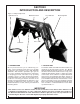
SECTION V ASSEMBLY CAUTION 12. Before operating the machine, thoroughly read the operation section of this manual. THE FOLLOWING SAFETY PRECAUTIONS SHOULD BE THOROUGHLY UNDERSTOOD BEFORE ATTEMPTING MACHINE ASSEMBLY. 1. Do not lift heavy parts or assemblies. Use crane, jack, tackle, fork trucks, or other mechanical devices. 2 13. Before operating, read the maintenance section of this manual to be sure that any parts requiring lubrication such as gearboxes are full to avoid any possible damage. 14.
Figure 5-3 Cuff Arrangements Figure 5-1 Parking Stands Installed LOADER MODELS 2426 QT, 3226 QT Subframe Cuff With Welded-On Bolt Fixed Pivot Pin LOADER MODELS 2446 QT, 2846 QT F. Connect hydraulic hoses to loader as shown in Figure 5-2. If optional hydraulic valve is used, refer to paragraphs 5-2 and 5-3 for valve and stand assembly instructions. G. Install cuffs, pins, washers, bolts, and nuts as shown depending on your particular model loader.
Figure 5-4 Valve Stand Assembly Optional Mounting Bracket Shield 1/2 x 1-1/2” Operational Decal 3/8 x 1-1/4” 5/8 x 6-1/2” (2) 5/16 X 2-1/2” 5/16 X 3” 5/16 x 3” Mounting Bracket 1/2 X 3” Valve Plate 1/2 X 1-1/2” 5/16 X 1” Tube 5/8 X 6-1/2” Mounting Plate Optional Brace C. Attach mounting tube to bracket using 1/2 x 3” bolts, lockwashers and nuts. The slotted hole also requires a flatwasher, as shown. D. Attach valve plate to tube using U-bolts, lockwashers and nuts.
5-3 OPTIONAL HYDRAULIC VALVE PLUMBING INSTRUCTIONS D. Remove open center plug. E. Install the closed center plug furnished with valve. Note: When converting to closed center configuration open center plug is removed from valve and installed in sleeve of closed center plug assembly. F. Install valve operational decal on valve shield. A. Mount valve assembly to valve plate using fasten ers provided. B. Plumb valve as shown in Figure 5-5. C. This valve is set for an open center tractor hydraulic system.
5-4 BASIC POWER BEYOND PLUMBING INSTRUCTIONS IMPORTANT When loader hydraulics are disconnected from tractor hydraulics, hoses A & B must be connected to complete tractor hydraulic circuit. FAILURE TO DO THIS WILL CAUSE SERIOUS DAMAGE TO TRACTOR HYDRAULIC SYSTEM. Open Center Plug Figure 5-6 Power Beyond Plug NOTE More detailed assembly instructions are furnished with individual Power Beyond Kits.
5-5 FORK LIFT OPTION Insert fork support rods through main frame and fork tubes. Secure in place with nuts and bolts provided. Fork Support Rod Bolt & Nut Mainframe 5-6 BALE SPEAR OPTION Insert spears into frame and fasten with roll pins and eccentric nut as shown. Torque nut to 470 - 505 ft./lbs. Tapered side of nut must be assembled against frame.
5-7 OPTIONAL BUCKET ITEMS ASSEMBLY SPILL GUARD ATTACHMENT SPILL GUARD 1. Place spill guard on bucket & center. 2. Mark hole centers for attaching fasteners. Allow clearance for side cutting edges on bolts in side plates if necessary. 3. Remove spill guard and drill 9/16” holes.
SAFETY DECALS To promote safe operation, Bush Hog supplies safety decals on all products manufactured. Because damages can occur to safety decals either through shipment, use or reconditioning, Bush Hog will, upon request, provide safety decals for any of our products in the field at no charge. Contact your authorized Bush Hog dealer for more information. REAR VIEW OF SUBFRAME Decals 25H46070, 25H46071, 25H46010 and 25H46012 are located on the left side of the subframe.
TORQUE SPECIFICATIONS Proper toque for American fasteners used on Bush Hog equipment. Recommended Torque in Foot Pounds (Newton Meters).* AMERICAN Bolt Head Markings W RENCH S IZ E (IN .) “ A ” B O L T D IA M E T E R (IN .
P.O. Box 1039 l Selma, AL 36702-1039 Telephone (334) 874-2700 l www.bushhog.