BUSH HOG ® GRASS CATCHER Model GC-250 908 ASSEMBLY l OPERATION l MAINTENANCE $4.
CONGRATULATIONS! You have invested in the best implement of its type on the market today. The care you give your Bush Hog implement will greatly determine your satisfaction with its performance and its service life. We urge a careful study of this manual to provide you with a thorough understanding of your new implement before operating, as well as suggestions for operation and maintenance. If your manual should become lost or destroyed, Bush Hog will be glad to provide you with a new copy.
GRASS CATCHER Model GC-250 SECTION TABLE OF CONTENTS PAGE SECTION Warranty . . . . . . . . . . . . . . . . . . . . . . . . . . . . . 2 IV Federal Laws and Regulations . . . . . . . . . . . . 3 I II III Safety . . . . . . . . . . . . . . . . . . . . . . . . . . . . . 4-8 PAGE OPERATING INSTRUCTIONS . . . . . . . . . . . . 14 4-1 General Safety. . . . . . . . . . . . . . . . . . . . . . . . . . 14 4-2 Operating Tips on Mowing . . . . . . . . . . . . . . . . 14 4-3 Emptying the Collection Bags . . .
LIMITED WARRANTY OOOOOOOOOOOOOOOOOOOOOOOOOOOOOOO Bush Hog warrants to the original purchaser of any new Bush Hog equipment, purchased from an authorized Bush Hog dealer, that the equipment be free from defects in material and workmanship for a period of one (1) year from date of retail sale. The obligation of Bush Hog to the purchaser under this warranty is limited to the repair or replacement of defective parts.
IMPORTANT FEDERAL LAWS AND REGULATIONS* CONCERNING EMPLOYERS, EMPLOYEES AND OPERATIONS. *(This section is intended to explain in broad terms the concept and effect of the following federal laws and regulations. It is not intended as a legal interpretation of the laws and should not be considered as such). U.S. Public Law 91-596 (The Williams-Steiger Occupational and Health Act of 1970) OSHA This Act Seeks: “...
IMPORTANT SAFETY PRECAUTIONS Training Carefully read all of the safety instructions and decals in the safety section. This information could help you, your family, pets or bystanders avoid injury. • Regard the Bush Hog GC-250 Grass Catcher as a piece of power equipment and teach this regard to all who operate this unit. • Before operating your Grass Catcher, carefully read and understand this manual and the operator’s manual for your mower in their entirety.
• Use EXTREME caution when mowing Slopes • Greater care must be taken and/or turning on slopes as loss of traction and/or tip-over could occur. The operator is responsible for safe operation on slopes. increases. • Always avoid sudden starting or stopping ! CAUTION Mowing on wet grass or steep slopes can cause sliding and loss of control. Wheels dropping over edges can cause rollovers, which may result in serious injury, death or drowning.
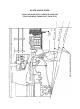
SLOPE ANGLE GUIDE ALIGN THIS EDGE WITH A VERTICAL SURFACE (TREE. BUILDING, FENCE POST. POLE, ETC.
Safety Alert Symbol This Safety Alert Symbol means: “ATTENTION! BECOME ALERT! YOUR SAFETY IS INVOLVED!” This symbol is used to call attention to safety precautions that should be followed by the operator to avoid accidents. When you see this symbol, carefully read the message that follows and heed its advice. Failure to comply with safety precautions could result in death or serious bodily injury.
SAFETY DECALS To promote safe operation, Bush Hog supplies safety decals on all products manufactured. Because damage can occur to safety decals either through shipment, use or reconditioning, Bush Hog will, upon request, provide safety decals for any of our products in the field at no charge. Contact your authorized Bush Hog dealer for more information.
SECTION I INTRODUCTION AND DESCRIPTION SECTION II PREPARATION FOR INSTALLATION 2-1 Unpacking the Grass Catcher Figure 1 Carefully remove wrapping from around shipping crate and open boxes. Remove and sort all parts for easy identification. GC-250 GRASS CATCHER KIT CONTENTS 1-1 Introduction We are pleased to have you as a return Bush Hog customer.
SECTION III INSTALLATION AND SETUP B. The front weight is 3” x 4” x 18” long and weighs approximately 60 pounds. If you are not capable of lifting 60 pounds with ease, get help to perform this step. 3-1 Installing the Weight Kit Place the weight into the weight brackets with the 4” side down. Make sure the weight is completely into the brackets and not sitting on the edge of the brackets. See (Figure 4). When the weight is securely in place reinstall the foot panel.
B. Attach the right hand and left hand frame brackets and the optional ROPS mounting brackets to the outside of the ZT frame as shown in (Figure 8). Use four 3/8” x 3/4” bolts or (six 3/8” x 1” bolts if ROPS is attached) and 3/8” locknuts.Tighten all fasteners, If ROPS is attached leave all fasteners slightly lose and proceede to next step. With the Boot assembly in place make sure the 5/16” flange nuts are loose enough to allow the bolts to slide in the slotted hole.
D. Place the lower frame assembly to the ends of the frame bracket s as shown in (Figure 10). Use Four 3/8” x 3/4” bolts and 3/8” Nyloc locknuts from the hardware package. Figure 10 Figure 13 Inlet Tube Frame Bracket Ends 3/8” x 3/4” Bolts 3/8” Nyloc Locknuts Inlet Tube Lip Top Assembly C. After the inlet tube is in place attach the 6” hose to the inlet tube and the boot assembly. Use the two large hose clamps supplied in the bag of hardware.
3-6 Blade Installation B. Install the completed assemblies into the support frame and close the plastic top. Refer to (Figure 16) Note:Blade kits will either have two 18.1” long blades for the 36” mower deck or two 21.1” long blades for the 42” mower deck.
SECTION IV OPERATING INSTRUCTIONS 4-3 Emptying the Collection Bags ! WARNING! To determine when the collection bags are full, follow the following steps: 4-1 General Safety A. Stop the forward movement of the mower. B. Disengage the mower deck. C. Turn the Ignition off and remove key. D. Engage the parking brake. E. Once the parking brake has been engaged, and only then, walk behind the mower and check the collection bags by lifting the plastic top.
SECTION V MAINTENANCE A. Remove the collection hose and boot assembly from the deck and the inlet tube by loosening the hose clamp and sliding the hose off the inlet tube.. B. Raise the top and remove bags, if bags contain debris empty them. Lay bags aside and close top. With the aid of another worker lift the grass catcher frame and top assembly from the hitch. NOTE: The grass catcher hitch does not need to be removed from the mower. 5-1 Maintenance Checklist Before each use: 1.
5-2 Recommended Maintenance Schedule Maintenace Service Intrevals After first 10 hours of operation Before each use Before storage Storage Storing the Grass Catcher 1. Clean the Grass Catcher; refer to Cleaning the Grass Catcher. 2. Inspect the Grass Catcher for damage; refer to Inspecting the Grass Catcher. 3. Make sure the grass bags are empty and thoroughly dry. 4. Store the Grass Catcher in a clean, dry place, out of direct sunlight. This protects the plastic parts and extends the life of the bagger.
TORQUE SPECIFICATIONS AMERICAN Proper toque for American fasteners used on Bush Hog equipment. Recommended Torque in Foot Pounds (Newton Meters).* Bolt Head Markings WRENCH SIZE (IN.) “A” BOLT DIAMETER (IN.
NOTES