BUSH HOG ® Gasoline Trailed Rotary Cutter MODEL GT 4 8 Operator’s Manual ASSEMBLY ● OPERATION ● MAINTENANCE 600 $4.
CONGRATULATIONS! You have invested in the best implement of its type on the market today. The care you give your Bush Hog implement will greatly determine your satisfaction with its performance and its service life. We urge a careful study of this manual to provide you with a thorough understanding of your new implement before operating, as well as suggestions for operation and maintenance. If your manual should become lost or destroyed, Bush Hog will be glad to provide you with a new copy.
GT 48 Operator’s Manual TABLE OF CONTENTS SECTION/PARA SECTION/PARA PAGE I II PAGE III MAINTENANCE . . . . . . . . . . . . . . . . . . . .12 3-1 Maintenance Check List . . . . . . . . . .12 3-2 Belt Adjustment . . . . . . . . . . . . . . . . .12 3-3 Belt Replacement . . . . . . . . . . . . . . .12 3-4 Hub Bearing Replacement . . . . . . . .13 3-5 Blade Replacement . . . . . . . . . . . . . .13 3-6 Troubleshooting . . . . . . . . . . . . . . . . .13 Warranty . . . . . . . . . . . . . . . . . . . . .
BUSH HOG® LIMITED WARRANTY ✯✯✯✯✯✯✯✯✯✯✯✯✯✯✯✯✯✯✯✯✯✯✯✯✯✯✯✯✯✯✯ Bush Hog warrants to the original purchaser of any new Bush Hog equipment, purchased from an authorized Bush Hog dealer, that the equipment be free from defects in material and workmanship for a period of one (1) year for non-commercial, state, and municipalities’ use and ninety (90) days for commercial use from date of retail sale.
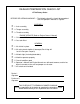
DEALER PREPARATION CHECK LIST GT 48 Rotary Cutter BEFORE DELIVERING MACHINE — The following check list should be completed. Use the Operator’s Manual as a guide. ASSEMBLY ❒ ❒ ❒ 1. Axle assembly 2. Tongue assembly 3. Throttle assembly ENGINE SERVICE (Refer to Engine Owner’s Manual) ❒ ❒ 1. Oil reservoir filled 2. Gas tank filled GENERAL ❒ ❒ 1. All shields in place 2. All safety decals legible (If damaged, Bush Hog will furnish free upon request) ❒ ❒ ❐ ❒ ❒ 3. All bolts tight (Including blade bolts) 4.
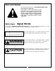
Safety Alert Symbol This Safety Alert Symbol means: “ATTENTION! BECOME ALERT! YOUR SAFETY IS INVOLVED!” This symbol is used to call attention to safety precautions that should be followed by the operator to avoid accidents. When you see this symbol, carefully read the message that follows and heed its advice. Failure to comply with safety precautions could result in death or serious bodily injury.
IMPORTANT SAFETY PRECAUTIONS This symbol is used to call attention to safety precautions that should be followed by the operator to avoid accidents. When you see this symbol, carefully read the message that follows and heed its advice. Failure to comply with safety precautions could result in death or serious bodily injury.
19. Keep the towing vehicle and cutter in good operating condition and keep safety devices in place. 20. Keep all nuts, bolts and screws tight to be sure the equipment is in safe working condition. 21. Never store the equipment with gasoline in the tank inside a building where fumes may reach an open flame or spark. Allow the engine to cool before storing in any enclosure. 22. To reduce fire hazard, keep the engine free of grass, leaves or excessive grease. 23.
IMPORTANT FEDERAL LAWS AND REGULATIONS* CONCERNING EMPLOYERS, EMPLOYEES AND OPERATIONS. *(This section is intended to explain in broad terms the concept and effect of the following federal laws and regulations. It is not intended as a legal interpretation of the laws and should not be considered as such). U.S. Public Law 91-596 (The Williams-Steiger Occupational and Health Act of 1970) OSHA This Act Seeks: “...
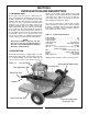
SECTION I INTRODUCTION AND DESCRIPTION attaches to the towing vehicle drawbar using a ball hitch and pin. The 48”, uplift blade bar assembly will cut pasture grass and weeds up to 3/4” diameter. This model rotary cutter is not meant for precision yard mowing or heavy brush cutting. 1-1 INTRODUCTION We are pleased to have you as a Bush Hog customer. Your Model GT 48 Rotary Cutter has been carefully designed to give maximum service with minimum down time.
SECTION II OPERATION 2-1 GENERAL SAFETY Figure 2-1 Only qualified people familiar with this operator’s manual information should operate this machine. Operator should wear hard hat, safety glasses and safety shoes. Before beginning operation, clear work area of any objects that may be picked up and thrown. Check for ditches, stumps, holes or other obstacles that could upset tractor or damage cutter. Always stop cutter engine before crossing driveways, walkways, roads or gravel areas.
Figure 2-3 Leveling Adjustment Rod Figure 2-4 Control Box Mounted On ATV Rack Figure 2-4 A Control Box Assy. 2-4 ELECTRIC START CONTROL BOX MOUNTING A. Attach mounting bracket to ATV rack using Ubolt. (Figure 2-4, 2-4A and Figure 4-2) B. Mount control box to mounting bracket by inserting quarter-turn fasteners into clip-on receptacle and turn 90 degrees. C. Disconnect battery pigtail from wiring harness.
● OPERATE ONLY WITH SIDE BANDS IN GOOD REPAIR. B. Release parking brake. C. Select lowest gear and begin cutting at a slow speed. Adjust speed to match terrain and grass thickness. When cutting thick grass, it may be necessary to adjust cutter lower in front to help prevent stalling. Care should be taken when turning sharply or backing that rear wheels of towing vehicle do not hit cutter. Cut up or down the face of slopes, not across the face. ● KEEP CHILDREN, PETS, AND BYSTANDERS AWAY FROM THE WORK AREA.
SECTION III MAINTENANCE 10. During operation, listen for abnormal sounds which might indicate loose parts, damaged bearings, or other damage. Repair or replace as necessary. WARNING BEFORE PERFORMING MAINTRENANCE INSPECTIONS OR WORK ON CUTTER, SHUT CUTTER ENGINE OFF AND DISCONNECT SPARK PLUG WIRE. FAILURE TO DO SO COULD RESULT IN ACCIDENTAL STARTING OF ENGINE CAUSING POSSIBLE INJURY OR DEATH. 40 HOURS 1. Grease blade hub assembly using grease gun and multi-purpose grease until grease purges out top seal.
C. Turn adjusting nut counterclockwise and slide engine rearward. Remove old belt. D. Install new belt onto pulleys. Do not pry belt onto pulley. E. Turn adjusting nut clockwise to tighten belt. Place enough tension on belt to allow not more than 1/2” and not less than 1/4” deflection. F. Tighten four engine stand bolts. G. Reinstall belt shield. Figure 3-3 Hub And Blade Assembly Hex Nuts Bushing Oil Seal Bearing Cone Outer Bearing Cup 3-4 HUB BEARING REPLACEMENT Hub Assembly A. Remove belt shield.
Table 3-1 General Troubleshooting TROUBLE PROBABLE CAUSE REMEDY Cutter engine stalls Cuttings not discharging Tilt cutter forward continuously Increase cutter height Towing cutter fast Decrease speed Cutting height too low Increase cutting height Cutter engine speed too slow Increase speed Engine malfunctioning Refer to engine owner’s manual Loose or broken belt Tighten /Replace Clutch malfunctioning Contact your Bush Hog dealer Blade is dull Sharpen blade Blade is upside down Reverse
AFTER COMPLETING ANY ASSEMBLY STEP, THOROUGHLY READ THE NEXT STEP IN THE ASSEMBLY INSTRUCTIONS BEFORE PROCEEDING WITH THAT STEP. 11. After completing assembly, thoroughly inspect the machine to be sure that all nuts, bolts, hydraulic fittings or any other fastened assemblies have been thogoughtly tightened. 12. After completing assembly, be sure that all safety locking devices or guards are in place. 13. Before operating the machine, thoroughly read the operation section of this manual. 14.
White Red (To Starter) To Battery Figure 4-2 Wiring Diagram White - + Green Red Red White Battery Pigtail Red Green To Key Switch Orange 4-2 ELECTRIC START CONNECTION TO ENGINE To Safety Kill Switch NOTE To mount control on ATV, see paragraph 2-4. E. Attach female terminals on end of jumper wires to key switch mounted in control box. Attach female terminal ends on green and orange wires to kill switch mounted in control box. (Figure 4-2) F. Push engine throttle down to limit of travel.
4-3 OPTIONAL FRONT ROLLER INSTALLATION (Figure 4-4 ) Figure 4-5 Bumper Guard Bolt rollers to deck front lip placing back plate on opposite side of deck lip. Bolts should be installed with head to underside of cutter. 4-4 OPTIONAL REAR ROLLER INSTALLATION (Figure 4-4) Bolt roller to rear deck band placing back plate to underside of deck. Bolts should be installed with head to underside of cutter.
SAFETY DECALS To promote safe operation, Bush Hog supplies safety decals on all products manufactured. Because damage can occur to safety decals either through shipment, use or reconditioning, Bush Hog will, upon request, provide safety decals for any of our products in the field at no charge. Contact your authorized Bush Hog dealer for more information. ❶❷❸ ❶ Part No. 96103 ❷ ❹ ❹ Part No. 81752 ❸ Part No. 81754 Part No.
TORQUE SPECIFICATIONS Proper toque for American fasteners used on Bush Hog equipment. Recommended Torque in Foot Pounds (Newton Meters).* AMERICAN Bolt Head Markings SAE Grade 2 (No Dashes) SAE Grade 5 (3 Dashes) ” lt Bo ter “B e m Dia Wrench Size “A” SAE Grade 8 (6 Dashes) METRIC Wrench Size “A” WRENCH SIZE (IN.) “A” BOLT DIAMETER (IN.
WARNING THE ENGINE EXHAUST FROM THIS PRODUCT CONTAINS CHEMICALS KNOWN TO THE STATE OF CALIFORNIA TO CAUSE CANCER, BIRTH DEFECTS OR OTHER REPRODUCTIVE HARM. ® BUSH HOG , L.L.C. P.O.