BUSH HOG ® MODEL RTC Rotary Tiller ASSEMBLY l OPERATION l MAINTENANCE 107 $4.
CONGRATULATIONS! You have invested in the best implement of its type on the market today. The care you give your Bush Hog implement will greatly determine your satisfaction with its performance and its service life. We urge a careful study of this manual to provide you with a thorough understanding of your new implement before operating, as well as suggestions for operation and maintenance. If your manual should become lost or destroyed, Bush Hog will be glad to provide you with a new copy.
Model RTC Rotary Tiller Operator’s Manual TABLE OF CONTENTS SECTION / PARA PAGE SECTION / PARA Warranty . . . . . . . . . . . . . . . . . . . . . . . .2 Dealer Preparation Check List . . . . . . .3 Safety Precautions . . . . . . . . . . . . . . . .4 Federal Laws And Regulations . . . . . .5 I PAGE 3-3 Operation . . . . . . . . . . . . . . . . . . . .9 3-4 Transporting . . . . . . . . . . . . . . . . . .9 IV MAINTENANCE . . . . . . . . . . . . . . . . .10 4-1 Maintenance Check List . . . . . . . .
LIMITED WARRANTY OOOOOOOOOOOOOOOOOOOOOOOOOOOOOOO Bush Hog warrants to the original purchaser of any new Bush Hog equipment, purchased from an authorized Bush Hog dealer, that the equipment be free from defects in material and workmanship for a period of one (1) year for non-commercial, state, and municipalities’ use and ninety (90) days for commercial use from date of retail sale. The obligation of Bush Hog to the purchaser under this warranty is limited to the repair or replacement of defective parts.
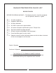
DEALER PREPARATION CHECK LIST ROTARY TILLERS BEFORE DELIVERING MACHINE — The following check list should be completed. Use the Operator’s Manual as a guide. r r r r r r r r r 1. Assembly completed. 2. Gearboxes filled with oil. 3. All fittings lubricated. 4. All shields in place and in good condition. 5. All fasteners torqued to specifications given in Torque Chart. 6. Slip clutch checked for proper operation. 7. All decals in place and readable. (See decal page.) 8.
IMPORTANT SAFETY PRECAUTIONS This symbol is used to call attention to safety precautions that should be followed by the operator to avoid accidents. When you see this symbol, carefully read the message that follows and heed its advice. Failure to comply with safety precautions could result in serious bodily injury.
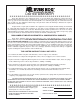
IMPORTANT FEDERAL LAWS AND REGULATIONS* CONCERNING EMPLOYERS, EMPLOYEES AND OPERATIONS. *(This section is intended to explain in broad terms the concept and effect of the following federal laws and regulations. It is not intended as a legal interpretation of the laws and should not be considered as such). U.S. Public Law 91-596 (The Williams-Steiger Occupational and Health Act of 1970) OSHA This Act Seeks: “...
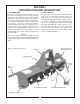
SECTION l INTRODUCTION AND DESCRIPTION 1-1 INTRODUCTION We are pleased to have you as a Bush Hog customer. Your Bush Hog Rotary Tiller has been carefully designed to give maximum service with minimum down time. This manual is provided to give you the necessary operating and maintenance instructions for keeping your rotary tiller in top operating condition. Please read this manual thoroughly. Understand what each control is for and how to use it.
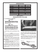
SPECIFICATIONS Model RTC40 Model RTC48 39-1/4” 48-1/4” 44” 53” 4” N/A 4 4 4 5 3-point Cat. I only 540 rpm 250 rpm 24 6” 17 ozs. 308 lbs. 335 lbs. Tilling width Overall width Offset Blades per flange No. of flanges Hitch PTO speed Rotor speed Max. recommended HP Max.
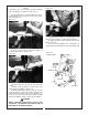
NOTE If driveline is the correct length, omit the following steps “G” through “J” and proceed to step “K”. Figure 2-5 G. Clamp driveline in a well padded vice to prevent damage to the shield. Cut off shield where marked. (Figure 2-3) Figure 2-3 L. Adjust lower lift arm to level tiller right to left. Refer to tractor operator’s manual for instructions. M. Adjust top link of tractor 3-point hitch to level tiller front to rear. N.
SECTION III OPERATING INSTRUCTIONS Tractor forward speed and rear shield adjustment (Figure 3-1) will regulate the finished results or tilth of soil. Traveling at the slowest forward speed with rear deflector fully lowered will give finest possible finish. This deflector adjustment is good for mulching, mixing, and burying weeds, fertilizer, etc. The more you increase forward speed and deflector height, the coarser the finished results will be.
SECTION IV MAINTENANCE AFTER EACH USE 1. Clean all debris from machine especially underside of deck and affixed decals. Replace any missing or illegible decals. 4-1 MAINTENANCE CHECK LIST Perform scheduled maintenance as outlined below. Lower machine to ground, turn off tractor and set parking brake before doing maintenance inspections or work. Some checks may require raising machine off ground and supporting with blocks.
NOTE: In some instances, sliding the yoke shield back will make lubrication, inspection and cleaning of the universal joints more convenient. Proceed as follows: 1. Using a flat blade screwdriver, rotate the fastening pin in its seat 1/2 turn until the head of the pin becomes unlocked in its housing on the cones. (Figure 4-2) 4. Remove the cones from the half-joint. (Figure 4-5) Figure 4-5 Figure 4-2 5.
4-3 BLADE REPLACEMENT 4-4 SLIP CLUTCH OPERATIONAL CHECK WARNING After tiller has been stored for 30 days or more, perform the following operational check: THE TILLER CAN FALL FROM HYDRAULIC SYSTEM FAILURE. TO AVOID SERIOUS INJURY OR DEATH, SECURELY SUPPORT TILLER BEFORE WORKING UNDERNEATH. A. Loosen eight nuts retaining clutch springs exactly one full turn. B. With tiller blades firmly on ground and tractor at idle speed, engage tractor PTO drive for 2-3 seconds.
4-7 TROUBLESHOOTING ment parts are necessary, contact your authorized Bush Hog dealer. Please have ready your machine name, model number, serial number, purchase date, and exact cause or description of problem. Troubleshooting procedures are listed in Table 4-1 below.
SECTION V DEALER ASSEMBLY WARNING THE FOLLOWING SAFETY PRECAUTIONS SHOULD BE THOROUGHLY UNDERSTOOD BEFORE ATTEMPTING MACHINE ASSEMBLY 1. Wear personal protective equipment such as, but not limited to, protection for eyes, ears, feet, hands and head when operating or repairing the equipment. Do not wear loose clothing or jewelry that may catch on equipment moving parts. 2. Do not lift heavy parts or assemblies. Use crane, jack, tackle, fork trucks or other mechanical devices. 3.
NOTICE: Refer to Figures 1-1, 3-1, 4-1 and 5-1 for visual reference to aid assembly. F. Place lower hitch pin brackets on front cross member of frame and fasten into position using M12 U-bolts and flanged locknuts. Notice that the hitch pin brackets can be positioned to best match the lift arms on your particular tractor. G. Attach one end of rear deflector adjustment chain to rear deflector with the clevis provided. The other end will fit into the slot next to the gearbox. A.
SAFETY DECALS To promote safe operation, Bush Hog supplies safety decals on all products manufactured. Because damage can occur to safety decals either through shipment, use or reconditioning, Bush Hog will, upon request, provide safety decals for any of our products in the field at no charge. Contact your authorized Bush Hog dealer for more information. Part No. 78413 Part No. 81067 Part No.
TORQUE SPECIFICATIONS Proper toque for American fasteners used on Bush Hog equipment. Recommended Torque in Foot Pounds (Newton Meters).* AMERICAN Bolt Head Markings SAE Grade 2 (No Dashes) SAE Grade 5 (3 Dashes) lt ” Bo er “B t e m Dia Wrench Size “A” B O L T D IA M E T E R (IN .) “ B ” A N D T H R E A D S IZ E SAE GRADE 2 7/16 1/4 - 2O UNC 7/16 1/4 - 28 UNF 1/2 1/2 W RENCH S IZ E (IN .
P.O. Box 1039 l Selma, AL 36702-1039 Telephone (334) 874-2700 l www.bushhog.