
User guide


10
7] Internal Adjustments
The SOC 1.1 has a number of internal trimpots to set up the ratio calibration and the gain
reduction metering circuit. Full line up is a relatively complicated procedure beyond the
scope of this manual, and should only be required if a LDR/LED module is replaced.
Instructions for full alignment can be obtained by contacting your supplier or Buzz Audio
directly.
• VU Meter Calibration.
IMPORTANT NOTE – the LDR module inside the SOC 1.1 is sensitive to external light so do not
perform any alignments in high light conditions. A black cloth should be laid over the LDR
modules (little black boxes with a dab of paint) to prevent light entering.
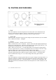
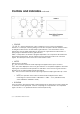
See page 10 for the location of trimpots.
• Set the front panel controls as follows:
Drive = 0 (fully anti-clockwise)
Output = 0dB (fully anti-clockwise)
Attack = Auto (middle)
Ratio = 2 (fully anti-clockwise)
Release = Auto (fully clockwise)
Meter = I/P (up)
Bypass = Bypass (up)
Link = Separate (up)
1] With the power off, remove the top panel and locate the Meter board directly behind the
switch board of the SOC 1.1 channel. Please observe safety precautions when removing the
top cover.
2] Adjust the V.U. meter mechanical zero (little black screwdriver adjustment on the rear of
the meter barrel) for a mechanical zero.
3] Connect an accurate audio voltmeter to the SOC 1.1 output. Feed into the input a 1kHz
+4dBu (1.23V rms) signal. The level on the external audio voltmeter should read +4dBu.
4] Apply power and switch the Bypass switch to IN, the external audio voltmeter should also
read +4dBu (+/- 0.5 dB)
5] Locate the VU CAL trimpot on the meter board and adjust it for
0 V.U. indication on the SOC 1.1 V.U. meter. Change the Meter switch to O/P and check
that the SOC 1.1 meter also indicates 0 V.U. (+/- 0.5dB).
6] Remove the input signal, change the Meter switch to G/R and locate the METER ZERO
trimpot. Adjust this to obtain a 0 V.U. indication.
• Problems?
Contact your dealer or Buzz Audio.
SOC 1.1 USERS MANUAL VERSION-4 PAGE 10