
User guide


3
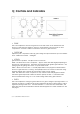
2] Connections
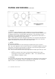
• Audio Input.
The XLR female style input connector is wired as follows;
Pin 1 = Signal Ground (common)
Pin 2 = Signal Hot (+)
Pin 3 = Signal Cold (-)
• Audio Output.
The XLR male style output connector is wired as follows;
Pin 1 = Signal Ground (common)
Pin 2 = Signal Hot (+)
Pin 3 = Signal Cold (-)
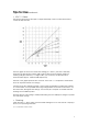
Both inputs and outputs are electronically balanced. The standard operating input sensitivity
for the SOC 1.1 is +4dBu (1.23V rms). This input level will give a 0 V.U. reading on the meters.
Other input sensitivities (eg, -10dBv) can be supplied from the factory.
• Note…
The pin 1 Signal Ground connection is intended for connecting cable SHIELDS. When
connecting the SOC 1.1 to other devices, it is not always necessary to connect the shield at
both ends of the cable. This may help prevent earth loops occurring.
The normal practice is to connect the shield at the receiving (input) end and leave the send
(output) end “earth free”.
FOR SAFETY REASONS THE SOC 1.1 SHOULD ALWAYS BE MAINS
EARTHED. RESIST THE TEMPTATION TO REMOVE THE EARTH TO
GET RID OF HUM. FIX IT ELSEWHERE IN THE SYSTEM.
SOC 1.1 USERS MANUAL VERSION-4 PAGE 3