, 2, 3, and 4-Gas Detector Operator’s Manual
Limited Warranty and Limitation Liability BW Technologies LP (BW) warrants the product to be free from defects in material and workmanship under normal use and service for a period of two years, beginning on the date of shipment to the buyer. This warranty extends only to the sale of new and unused products to the original buyer.
GasAlertMicroClip XT Introduction The operator’s manual provides basic information for the GasAlertMicroClip XT. For complete operating instructions, refer to the GasAlertMicroClip XT Technical Reference Guide provided on the CD-ROM. The GasAlertMicroClip XT (“the detector”) warns of hazardous gas at levels above user-defined alarm setpoints. The detector is a personal safety device. It is your responsibility to respond properly to the alarm.
GasAlertMicroClip XT Operator’s Manual • Calibrate the detector before first-time use and then on a regular schedule, depending on use and sensor exposure to poisons and contaminants. BW recommends calibrating at least once every 180 days (6 months). • Caution: High off-scale readings may indicate an explosive concentration. • The combustible sensor is factory calibrated to 50% LEL methane. If monitoring a different combustible gas in the %LEL range, calibrate the sensor using the appropriate gas.
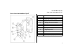
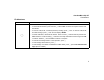
GasAlertMicroClip XT Parts of the GasAlertMicroClip XT Parts of the GasAlertMicroClip XT Item Description 1 IntelliFlash 2 Visual alarm indicators (LEDs) 3 Alligator clip 4 Charging connector / IR interface 5 Pushbutton 6 Carbon monoxide (CO) sensor 7 Hydrogen sulfide (H2S) sensor 8 Oxygen (O2) sensor 9 Combustible (LEL) sensor 10 Audible alarm 11 Liquid crystal display (LCD) 3
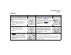
GasAlertMicroClip XT Operator’s Manual Display Elements Item 1 8 2 7 3 6 5 4 4 Description 1 Alarm condition 2 Automatically zero sensor 3 Numeric value 4 Stealth mode 5 Battery life indicator 6 Gas identifier bars 7 Gas cylinder 8 Automatically span sensor
GasAlertMicroClip XT Pushbuttons Pushbuttons Pushbutton Description • To activate the detector, press C. • To deactivate the detector, press and hold C until the OFF countdown is complete and the LCD deactivates. • To view the TWA, STEL, and MAX (maximum) readings, press C twice. To clear the TWA, STEL, and MAX readings, press C when the LCD displays RESET. C • To initiate calibration, deactivate the detector. Press and hold C while the detector performs the OFF countdown.
GasAlertMicroClip XT Operator’s Manual Sensor Poisons and Contaminants Several cleaners, solvents, and lubricants can contaminate and cause permanent damage to sensors. Before using cleaners, solvents, and lubricants in close proximity to the detector sensors, read the following caution and table. a Caution Use only the following BW Technologies by Honeywell recommended products and procedures: • Use water based cleaners. • Use non-alcohol based cleaners. • Clean the exterior with a soft, damp cloth.
GasAlertMicroClip XT Calibration Calibration Procedure a Caution Calibrate only in a safe area that is free of hazardous gas in an atmosphere of 20.9% oxygen. 1. Press and hold C as the detector performs the OFF countdown. Continue holding C when the LCD briefly deactivates. Display Procedure Display 4. When K flashes, connect the gas cylinder (refer to page 8) and apply gas at a flow rate of 250-500 ml/min.
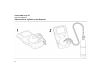
GasAlertMicroClip XT Operator’s Manual Attach the Gas Cylinder to the Detector 8
GasAlertMicroClip XT Bump Test Bump Test 9
GasAlertMicroClip XT Operator’s Manual Alarms Refer to the following table for information about alarms and corresponding screens. If Stealth mode is enabled, the audible and visual alarms are disabled. Only the vibrator alarm activates.
GasAlertMicroClip XT Alarms Alarm Sensor Alarm • During startup Error [sensor name] displays • During normal operation Err displays Low Battery Alarm • Sequence of 10 rapid sirens and alternating flashes with 7 seconds of silence in between (continues for 15 minutes) • and L flash, LOW BAT displays, and the vibrator alarm activates • After 15 minutes of the Low Battery alarm, the Automatic Shutdown Alarm sequence begins • OFF displays before deactivating Display Alarm Display Confidence Beep and Inte
GasAlertMicroClip XT Operator’s Manual User Options Menu To modify the user options, connect the detector to the IR Link adapter and open Fleet Manager II. Refer to the Fleet Manager II Operator’s Manual for complete instructions. The following are the available user options: 1. Sensors (H2S, CO, LEL, and O2) • Sensor Disabled: Disables the sensor. • Calibration Gas (ppm) / (%LEL) / (%O2): Defines the calibration gas concentration for each sensor.
GasAlertMicroClip XT Charging the Detector • Low Alarm Acknowledge: When enabled, the audible alarm can be disabled during a low alarm. The vibrator, LEDs, and LCD remain enabled. For H2S, CO, and LEL sensors only. • Datalog Interval (seconds): Enter a value (5-120 seconds) to define how often a datalog is recorded. Datalog interval cannot be defined with configuring the detector with the IR Link.
GasAlertMicroClip XT Operator’s Manual To charge the battery, complete the following: 3. Allow the battery to charge for 2-3 hours. 1. Deactivate the detector. Insert the charging adapter plug into an AC outlet. 4. To reach full battery capacity, allow the battery to fully charge and discharge three times. 2. Connect the charging adapter to the detector IR interface. Refer to the following illustration. 5. Charge the battery after each workday.
GasAlertMicroClip XT Maintenance To replace a sensor or sensor filter, refer to the following illustration, table, and procedures. Item Description 1 Front shell 2 LEL sensor 3 PCB 4 PCB screws (2) 5 Rear shell 6 Machine screws (6) 7 Sealing rib 8 CO sensor 9 H2S sensor 10 O2 sensor 11 Sensor filter 1. Deactivate the detector. On a clean surface, place the detector face down. 2. Remove the six machine screws from the rear shell.
GasAlertMicroClip XT Operator’s Manual Replacing the sensor filter 1. Note the placement of the PCB to ensure it is replaced correctly. Remove the two screws on the PCB. Remove the PCB carefully. 1. Note the placement of the PCB to ensure it is replaced correctly. Remove the two screws on the PCB. Remove the PCB carefully. a Caution a Caution Ensure no damage occurs to the battery. Ensure no damage occurs to the battery. 2. Remove the old sensor filter. It may be stuck to the sensors.
GasAlertMicroClip XT Maintenance Replacing the oxygen sensor 2. Note Detectors that are configured for 1, 2, or 3 gases may contain a dummy sensor in one of the four sensor locations. 1. Gently remove the circular rigidified flex PCB atop the sensor from the metal sensor posts. Take care not to tear the flex cable. Note the placement of the PCB to ensure it is replaced correctly. Remove the two screws on the PCB. a Caution Ensure no damage occurs to the battery. 3. Lift the PCB straight up.
GasAlertMicroClip XT Operator’s Manual • Visually inspect the battery to ensure no damage has occurred. • When replacing the rear shell, ensure the charging pins (bottom of inside rear shell) are aligned with the corresponding holes on the PCB. • Press the front and rear shells together firmly to ensure a proper seal. Ensure the front and rear shell have a uniform, tight 1/16 in. (1 mm) seal on all sides of the detector. • When replacing the screws, they must be seated properly to prevent cross threading.
GasAlertMicroClip XT Specifications Specifications Instrument dimensions: 11.25 x 6.00 x 2.89 cm (4.4 x 2.4 x 1.1 in.) Weight: 170 g (6.0 oz.
GasAlertMicroClip XT Operator’s Manual period, low alarm acknowledge, IntelliFlash, confidence beep, and IntelliFlash interval Battery operating time: 1 rechargeable lithium polymer battery 10 hours (typical) Year of manufacture: The detector's year of manufacture is determined from the serial number. The second and third number after the first letter determines the year of manufacture. E.g.
iERP: 131474-L3 D6567/0 [English] © BW Technologies 2010. All rights reserved.