Legacy Mobile Platform Troubleshooting Guide The iNetVu™ brand and logo are registered trademarks of C-COM Satellite Systems, Inc. © Copyright 2006 C-COM Satellite Systems, Inc. 1-877-iNetVu6 www.c-comsat.
Page 2 of 88 iNetVu Troubleshooting Guide Copyright © 2010. All rights reserved. C-COM Satellite Systems Inc. This document contains information, which is protected by copyright. All rights reserved. Reproduction, adaptation, or translation without prior written permission is prohibited, except as followed under the copyright laws. Both the iNetVu™ and C-COM names and logos are registered trademarks of C-COM Satellite Systems Inc. Intel® Pentium is a registered trademark of Intel Corporation.
Page 3 of 88 iNetVu Troubleshooting Guide FCC and INDUSTRY CANADA INFORMATION TO THE USER: The FCC and Industry Canada have imposed the following conditions when operating, installing and deploying iNetVu™ Mobile Earth Stations and is mandatory for all installations made within the Continental United States and Canada as well as Hawaii, Alaska, Puerto Rico, the U.S. Virgin Islands and other U.S. Territories. The FCC requires that a certified installer perform the installation.
Page 4 of 88 iNetVu Troubleshooting Guide extraordinary precautions and measures are used to prevent satellite interference or exposure to harmful radiation. C-COM reserves the rights to immediately suspend without liability or previous notice the operation of the earth station upon detection of a deviation from its installation or operational requirements until the deviation is corrected.
Page 5 of 88 iNetVu Troubleshooting Guide C-Com Satellite Systems Global Headquarters 2574 Sheffield Road Ottawa, Ontario, Canada K1B 3V7 Phone: +1-613-745-4110 Fax: +1-613-745-7144 General Inquiries: info@c-comsat.com Dealer Information: dealer@c-comsat.com Support Services: support@c-comsat.
Page 6 of 88 iNetVu Troubleshooting Guide Table of Contents INTRODUCTION ................................................................................................................................. 8 7000 CONTROLLER SOFTWARE & FIRMWARE UPGRADE ........................................................... 9 UNINSTALLING THE CURRENT SOFTWARE ........................................................................................... 10 NEW SOFTWARE AND DRIVERS INSTALLATION PROCEDURE ......................
Page 7 of 88 iNetVu Troubleshooting Guide GPS ................................................................................................................................................... 60 GPS FAILED ..................................................................................................................................... 61 STOW ................................................................................................................................................
Page 8 of 88 iNetVu Troubleshooting Guide INTRODUCTION About This Manual This manual explains how to troubleshoot common errors on the iNetVu™ Mobile System. An electronic version of this manual is available on the C-COM FTP and Knowledge Base. C-COM Satellite Systems Inc.
Page 9 of 88 iNetVu Troubleshooting Guide 7000 CONTROLLER SOFTWARE & FIRMWARE UPGRADE Quick Tip: The software and firmware versions must match for normal operation. IMS Version 7.1.3 – 7.2.5 7.5.1 + RAM 512 MB 1 GB Minimum Requirements to run IMS Software Processor Clock Disk Space 800 MHZ 2.0 GHZ 50 Megs Of Free Space 100 Megs Of Free Space C-COM Satellite Systems Inc. Microsoft .NET Version N/A .NET Framework 3.
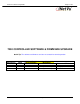
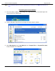
Page 10 of 88 iNetVu Troubleshooting Guide Note: This method describes the steps for upgrading to and from the new .NET GUI interface ver. 7.5.x Uninstalling the Current Software 1. Ensure the iNetVu software is not running. If it is, right click the icon on the bottom right of the screen and exit. As shown below. 2. Go to the Windows Control Panel and simply uninstall the iNetVu software. 3. Open “My Computer” then “Local Disk (C:)” then “Program Files” or “Program Files (x86)”.
Page 11 of 88 iNetVu Troubleshooting Guide New Software and Drivers Installation Procedure Applies to: iNetVu combined Software and Drivers Package version 7.5.5+ Note: Do not connect the Controller via USB until the drivers and software have been installed 1. If you are installing from the USB flash drive or have downloaded from the C-COM FTP, run the iNetVuSetup.exe file. 2. Click OK to continue.
Page 12 of 88 iNetVu Troubleshooting Guide 3. Continue through the Device Driver Installation Wizard. Click “Next” Click “Continue Anyway” Click “Finish” to continue. 4. Now continue through the iNetVu Software installation and close when complete. A new Icon will automatically be placed on the Desktop. 5. Now that the drivers and software package has been installed, connect the iNetVu 7000 Controller via USB to your PC. 6.
Page 13 of 88 iNetVu Troubleshooting Guide Select “No, not this time” Select “Install the software automatically” Click “Continue Anyway” Click “Finish” 7. Windows Vista and 7 users, the drivers should install automatically without any further user action. It’s normal for the 7000 driver to be displayed as iNetVu Controller 5000 8. You have successfully installed the 7000 iNetVu Drivers and Software. You can now continue updating the Controller firmware. C-COM Satellite Systems Inc.
Page 14 of 88 iNetVu Troubleshooting Guide Running the iNetVu Software on a 64bit Machine You may experience issues running the software on a 64bit version of Windows. To resolve this issue please follow these steps. The iNetVu 7000 Software should run normally under these conditions. 1. Right click the desktop shortcut and select “Properties”. 2. Select the Compatibility Tab and check “Run this program as an administrator” Click OK to save and close.
Page 15 of 88 iNetVu Troubleshooting Guide Updating the Firmware 1. Launch the iNetVu 7000 Mobile Software. Since the software is being upgraded, the Software and Firmware will not match. Please follow the steps below to update the Firmware. a) Once the controller is fully booted and the software is launched, the LCD should display what is shown below. If your results differ, please contact C-COM Technical support. Note: Screens may differ depending on Firmware. Ver. 7.5.
Page 16 of 88 iNetVu Troubleshooting Guide Verifying the Upgrade Completed Successfully 2. Right click on the current screen you are on, and select “About”. Verify both Software and Firmware versions are identical. 3. After the firmware update has completed, proceed to the “Maintenance” screen and verify that the platform type, Ver. and serial number match your configuration. Make any necessary changes “Send All” and wait for confirmation, then “Write EPROM”. C-COM Satellite Systems Inc.
Page 17 of 88 iNetVu Troubleshooting Guide CONTROLLER REPLACEMENT PROCEDURE This article describes the steps to take upon receiving a new controller replacement. Please note failing to perform these steps, will result in unfavorable results. Step 1: • Enter the mobile platform serial number into the iNetVu software. Select the proper platform type and Ver.
Page 18 of 88 iNetVu Troubleshooting Guide Step 2: • Assuming we have platform A1200B/C, Ver. 3.0 and serial number 5655, let’s input this into the software maintenance screen. Click “Send All” and wait for confirmation, then “Write EPROM”. C-COM Satellite Systems Inc.
Page 19 of 88 iNetVu Troubleshooting Guide Step 3: • The new controller must be calibrated with the existing mobile platform. • Proceed into the Maintenance screen and select the tab of the axis you wish to calibrate on the upper right. The only calibrations we need to perform are for the Azimuth (AZ) axis and Polarization (PL) axis. There is no importance of which is performed first, as long as both are done consecutively.
Page 20 of 88 iNetVu Troubleshooting Guide • Upon hitting “Calibrate AZ” or “Calibrate PL”, the software will automatically switch to the controls screen to commence the calibration. On the bottom right hand side a message under the status section, will display “AZ/PL Calibration” as shown below. • We must wait for this message to change to “System Idle” and only “System Idle” which is the official indication that the process is completed.
Page 21 of 88 iNetVu Troubleshooting Guide JAM ERRORS Quick Tip: The key to troubleshooting a Jam Error is to determine whether this is a Sensor or Mechanical failure. C-COM Satellite Systems Inc.
Page 22 of 88 iNetVu Troubleshooting Guide Error 0x9006 - EL Jam Error 1. If the Mobile Platform doesn’t physically move Possible Causes: • 7000 Controller • 15 Amp Fuse • Motor Cable • Internal Wiring Harness • Elevation Motor (actuator) • Over Stow (EL ST is enabling too late) a. Verify if 7000 Controller is outputting 12VDC. Disconnect the motor cable from the back of the controller, place the volt meter leads on pins 1 and 3 of the controller.
Page 23 of 88 iNetVu Troubleshooting Guide c. If voltage is shown, we will need to test voltage on the motor cable. Reconnect the motor cable to the controller and disconnect it from the base plate of the platform. Place the volt meter leads on pins A and B or 1 and 3 of the motor cable. Using the 7000 controllers front panel, select Elevation with HI SPEED on and hold +. Are you getting 12VDC? If no voltage is shown, it concludes the motor cable needs to be replaced.
Page 24 of 88 iNetVu Troubleshooting Guide f. Using the 7000 controller’s front panel, select Elevation with HI SPEED on and hold +, at the same time a colleague must try to lift the Platform. If Platform successfully rises, it concludes it was over stowed. Contact C-Com Technical Support for further assistance. g. If the Platform cannot rise with assistance, it concludes the Elevation motor (actuator) needs to be replaced. Contact C-Com Technical Support for assistance. C-COM Satellite Systems Inc.
Page 25 of 88 iNetVu Troubleshooting Guide 2. If the Mobile Platform physically moves but the angle doesn’t change Possible Causes: • Inclinometer (Tilt Sensor) • Sensor Cable • Internal Wiring Harness • 7000 Controller a. Test the Controller Sensor Pins for voltage. On the controller sensor connector test pins 9 and 18 for 12VDC. If you are getting power proceed to testing the Sensor Cable and Internal Wiring Harness. If you are not getting power please contact C-COM Technical Support.
Page 26 of 88 iNetVu Troubleshooting Guide EL Sensor Circuit: MIL Spec Connector EL Sensor Circuit: AMP Spec Connector C-COM Satellite Systems Inc.
Page 27 of 88 iNetVu Troubleshooting Guide Error 0x9007 - AZ Jam Error 1. If the Mobile Platform doesn’t physically move Possible Causes: • 7000 Controller • 15 Amp Fuse • Motor Cable • Internal Wiring Harness • Azimuth Motor • Insufficient Greasing Note: If the antenna physically rotates but jams in random locations please skip to step “e” a. Verify if 7000 Controller is outputting 12VDC.
Page 28 of 88 iNetVu Troubleshooting Guide c. If voltage is shown, we will need to test voltage on the Motor cable. Reconnect the Motor cable to the controller. Disconnect the Motor cable from the base plate of the Platform. Place the volt meter leads on pins F and E or 7 and 9 of the Motor cable. Using the 7000 controllers front panel, select Azimuth with HI SPEED ON and hold +. Are you getting 12VDC? If no voltage is shown, it concludes the Motor cable needs to be replaced.
Page 29 of 88 iNetVu Troubleshooting Guide Grease Application to Azimuth Gear Assembly Required Materials: • • • Phillips Screwdriver Standard Grease Gun Multi-Purpose Grease (Operating Temperature Range: -40c to 65c) ** Recommended: Shell AeroShell Grease 33 for improved low-temp spec, or equivalent.** Procedure: 1. Raise the iNetVu™ Mobile Platform. 2. Remove Elevation and Azimuth Covers. 3. Unscrew Azimuth Motor and lay on the Azimuth Plate. 4.
Page 30 of 88 iNetVu Troubleshooting Guide 1200/1500/1800 Azimuth Plate Grease Fitting Locations g. If no damage is found and the Platform is sufficiently greased, it concludes the Azimuth Motor needs to be replaced. Contact C-Com Technical Support for assistance. C-COM Satellite Systems Inc.
Page 31 of 88 iNetVu Troubleshooting Guide 2. If the Mobile Platform physically moves but the angle doesn’t change Possible Causes: • Azimuth Potentiometer • Sensor Cable • Internal Wiring Harness • 7000 Controller a. Test the Controller Sensor Pins for voltage. On the controller sensor connector test pins 25 and 26 for 5VDC. If you are getting power proceed to testing the sensor cable and wiring harness. If you are not getting power please contact C-COM Technical Support.
Page 32 of 88 iNetVu Troubleshooting Guide AZ Sensor Circuit: MIL Spec Connector AZ Sensor Circuit: AMP Spec Connector C-COM Satellite Systems Inc.
Page 33 of 88 iNetVu Troubleshooting Guide Error 0x9008 - PL Jam Error 1. If the Mobile Platform doesn’t physically move Possible Causes: • 7000 Controller • 5 Amp Fuse • Motor Cable • Internal Wiring Harness • Polarization Motor a. Verify if 7000 Controller is outputting 12VDC. Disconnect the motor cable from the back of the controller, place the volt meter leads on pins 4 and 6 of the controller. Using the 7000 controllers front panel, select Polarization with HI SPEED ON and hold +.
Page 34 of 88 iNetVu Troubleshooting Guide c. If voltage is shown, we will need to test voltage on the motor cable. Reconnect the motor cable to the controller. Disconnect the motor cable from the base plate of the platform. Place the volt meter leads on pins C and D or 4 and 6 of the motor cable. Using the 7000 controllers front panel, select Polarization with HI SPEED ON and hold +. Are you getting 12VDC? If no voltage is shown, it concludes the motor cable needs to be replaced.
Page 35 of 88 iNetVu Troubleshooting Guide 2. If the Mobile Platform physically moves but the angle doesn’t change Possible Causes: • Polarization Potentiometer • Sensor Cable • Internal Wiring Harness • 7000 Controller a. Test the Controller Sensor Pins for voltage. On the controller sensor connector test pins 25 and 26 for 5VDC. If you are getting power proceed to testing the sensor cable and wiring harness. If you are not getting power please contact C-COM Technical Support.
Page 36 of 88 iNetVu Troubleshooting Guide PL Sensor Circuit: MIL Spec Connector PL Sensor Circuit: AMP Spec Connector C-COM Satellite Systems Inc.
Page 37 of 88 iNetVu Troubleshooting Guide Note: This applies to platforms equipped with a polarization tilt sensor only 3. If the Mobile Platform physically moves but the angle doesn’t change (PL Tilt Sensor) Possible Causes: • Polarization Tilt Sensor (Platforms ver. 3.x (980/1200), 2.x (1800) only) • Sensor Cable • Internal Wiring Harness • 7000 Controller a. Test the Controller Sensor Pins for voltage. On the controller sensor connector test pins 9 and 18 for 12VDC.
Page 38 of 88 iNetVu Troubleshooting Guide The wiring harness for some platform versions has changed. To test the new wiring harness for Polarization Tilt continuity disconnect the Tilt Sensor from the wiring harness and set the volt meter to beep or continuity mode. Place one lead on pin (1, 2 or 3) to the wiring harness connector, and the other lead to the corresponding pin (A, J or R) on the platform connector plate. PL Tilt Sensor Circuit: MIL Spec Connector for 980 Platforms ver. 3.
Page 39 of 88 iNetVu Troubleshooting Guide PL Tilt Sensor Circuit: MIL Spec Connector for 1200 Ver. 3.x / 1800 Ver. 2.x Platforms C-COM Satellite Systems Inc.
Page 40 of 88 iNetVu Troubleshooting Guide 4. If the Mobile Platform physically moves but will not rotate to both extremes (Applies to 1.2M platforms only) The possible cause will be the Rear Bearing separating from the Rear Bushing. The separation will occur here a. Using the manually controls rotate the Polarization to both extremes. If you see the bushing separating in either the -90 or 90 positions they will need to be re-positioned. b.
Page 41 of 88 iNetVu Troubleshooting Guide OVER CURRENT PROTECTION C-COM Satellite Systems Inc.
Page 42 of 88 iNetVu Troubleshooting Guide Over-Current Protection Error Code Definition: *****Error Code--Stopping Motor, Setting System to IDLE ********* * 0x9000---EL Hardware Over-Current Protection * 0x9001---AZ Hardware Over-Current Protection * 0x9002---PL Hardware Over-Current Protection * 0x9003---EL Over current 3 seconds * 0x9004---AZ Over current 3 seconds * 0x9005---PL Over current 3 seconds Current used to move the Platform exceeds the fixed limit, which resulted in a current spike. 1.
Page 43 of 88 iNetVu Troubleshooting Guide Error: 0x9003 Elevation Over Current a. The Mobile Platform may have been obstructed by a foreign object and does not have enough clearance to elevate up or down. Ensure that the path of the Elevation arm has enough clearance for free movement. b. Go to Maintenance. Ensure Elevation Current and Speed is the default value (verify with 7000 Controller Manual). c. If the Low Platform Current is at default the Current can be increased in increments of 1.
Page 44 of 88 iNetVu Troubleshooting Guide SENSOR ERRORS Quick Tip: A red indicator on the iNetVu Controls screen indicates a critical failure. C-COM Satellite Systems Inc.
Page 45 of 88 iNetVu Troubleshooting Guide Error 0x8911 - Sensor Error Cause: 1. The sensor cable is not connected properly or the pins are bent, broken or corroded. 2. Specific Axis Potentiometer needs to be re-centered. (Angle Reading in RED or YELLOW) 3. Possible failed components. • • • • • Azimuth Potentiometer Polarization Potentiometer (Platform ver. 2.9 (980/1200), 1.9 (1800) and older only) Wiring Harness Sensor Cable 7000 Controller Solution: 1.
Page 46 of 88 iNetVu Troubleshooting Guide e. From the Controls Screen the AZ and PL Angles should be close to 0.00 as seen below. Ensure the AZ ST, and PL ST are activated f. If the angles are still incorrect, identify the specific axis that is flashing Red/Yellow. Example A: AZ Sensor Error Example B: PL Sensor Error g. Once the specific axis has been identified proceed to troubleshooting that angle by testing of the individual components.
Page 47 of 88 iNetVu Troubleshooting Guide Polarization Sensor Error Part A - Testing the Polarization POT: 1. Ensure the platform is physically in the center position on Polarization, by disconnecting the sensor cable and using the manually controls (visually verifying). 2. Remove the plastic Polarization cover using a Philips screwdriver. 3. Remove the POT and disconnect it from the wiring harness. 4. Rotate the gear CCW until you hit the hard stop.
Page 48 of 88 iNetVu Troubleshooting Guide Part B - Testing the Continuity of the Cabling. Use Polarization Sensor Circuit Diagram on the following page to confirm continuity of the cabling. Set the voltmeter to beeper or continuity mode. Please contact C-COM technical Support for further assistance. Sensor Cable Wiring Harness C-COM Satellite Systems Inc.
Page 49 of 88 iNetVu Troubleshooting Guide PL Sensor Circuit: MIL Spec Connector PL Sensor Circuit: AMP Spec Connector C-COM Satellite Systems Inc.
Page 50 of 88 iNetVu Troubleshooting Guide Azimuth Sensor Error Part A - Testing the Azimuth POT: 1. Ensure the platform is physically in the center position on Azimuth, by disconnecting the sensor cable and using the manually controls (visually verifying). 2. Remove the plastic Azimuth cover using a Philips screwdriver. 3. Remove the POT and disconnect it from the wiring harness. 4. Rotate the gear CCW until you hit the hard stop. From this point using a volt meter, set it to test for 2k ohms.
Page 51 of 88 iNetVu Troubleshooting Guide Part B - Testing the Continuity of the Cabling. Use Azimuth Sensor Circuit Diagram on the following page to confirm continuity of the cabling. Set the voltmeter to beeper or continuity mode. Please contact C-COM technical Support for further assistance. Sensor Cable Wiring Harness C-COM Satellite Systems Inc.
Page 52 of 88 iNetVu Troubleshooting Guide AZ Sensor Circuit: MIL Spec Connector AZ Sensor Circuit: AMP Spec Connector C-COM Satellite Systems Inc.
Page 53 of 88 iNetVu Troubleshooting Guide Centering the AZ/PL Potentiometer Azimuth Potentiometer AZ Pot locations: 1200, 1500, 1800 (left) 980, 750 (right) Gear underside of AZ Potentiometer To center the AZ Potentiometer: 1. Ensure the antenna is physically in the center position on Azimuth before continuing. Disconnect the sensor cable and manually move the antenna (visually verifying). 2. Locate and remove the azimuth potentiometer. 3.
Page 54 of 88 iNetVu Troubleshooting Guide To verify functionality: 1. Reconnect the sensor cable. 2. On the Controls Menu ensure that there are no red indicators flashing. 3. Proceed to the Maintenance Screen and ensure the Platform Type, Ver. and Serial Number is 4. 5. 6. 7. 8. correct for your configuration. Proceed to the Azimuth Tab. Ensure there is sufficient clearance for the dish to move and rotate. Click Calibrate AZ. When Calibration process is complete Stow the Dish.
Page 55 of 88 iNetVu Troubleshooting Guide Polarization Potentiometer Applies to Platforms ver. 2.9 (980/1200), 1.9 (1800) and older only PL Pot locations: 1200, 1500, 1800 (left) 980, 750 (right) Gear underside of PL Potentiometer To center the PL Potentiometer: 1. Ensure the antenna is physically in the center position on Polarization before continuing. 2. 3. 4. 5. 6. Disconnect the sensor cable and manually move the antenna (visually verifying). Locate and remove the PL Potentiometer.
Page 56 of 88 iNetVu Troubleshooting Guide To verify functionality: 1. Reconnect the sensor cable. 2. On the Controls Menu ensure that there are no red indicators flashing. 3. Proceed to the Maintenance Screen and ensure the Platform Type, Ver. and Serial Number is 4. 5. 6. 7. 8. correct for your configuration. Proceed to the Polarization Tab. Ensure there is sufficient clearance for the dish to move and rotate. Click Calibrate PL. When Calibration process is complete Stow the Dish.
Page 57 of 88 iNetVu Troubleshooting Guide COMPASS Quick Tip: Compass interference? Try overriding the compass and using full search. C-COM Satellite Systems Inc.
Page 58 of 88 iNetVu Troubleshooting Guide Compass value is not accurate Cause: A foreign object (e.g. metal, magnet) is radiating a magnetic field that is obscuring the compass from obtaining a reliable reading. Solution: 1. Ensure there are no foreign objects (e.g. metal, magnet) around the Mobile Platform. 2. Go to Maintenance. 3. Click Check Compass. 4. The Mobile Platform will now rotate on 90 ° intervals. 0, 90, 180, 270(-90). These figures are in relation to true North 5.
Page 59 of 88 iNetVu Troubleshooting Guide Compass Calibration Ensure that the front of the Vehicle is facing North. This END Faces South This END Faces North 1. Go to Maintenance / Compass Tab and Click Calibrate Compass. 2. Check the Compass once more, if all works well, you may continue. 3. If the compass still fails it will require replacement. If you are using DVB Search you may override the compass and use Full Search in this case. C-COM Satellite Systems Inc.
Page 60 of 88 iNetVu Troubleshooting Guide GPS Quick Tip: GPS failure? For emergency deployment, try GPS Override and enter the LAT/LONG manually. C-COM Satellite Systems Inc.
Page 61 of 88 iNetVu Troubleshooting Guide GPS Failed Cause 1: GPS Antenna is not connected. Solution 1: Verify GPS Antenna is securely connected. Cause 2: A foreign object is obstructing the GPS Antenna. Solution 2: Ensure there are no foreign objects obstructing the GPS Antenna from a clear view of the sky. Cause 3: Overcharge in the GPS Antenna. Solution 3: Turn off the Controller Unplug GPS Antenna from the back of the Controller and ground it. Wait 5 seconds.
Page 62 of 88 iNetVu Troubleshooting Guide For emergency deployment the GPS can be overridden and the LAT/LONG entered manually from the iNetVu 7000 Software or Web Interface. iNetVu 7000 Software 7000 Controller Web Interface C-COM Satellite Systems Inc.
Page 63 of 88 iNetVu Troubleshooting Guide STOW Quick Tip: The controller cannot stow the platform if any of the stow limit switches fail to enable. C-COM Satellite Systems Inc.
Page 64 of 88 iNetVu Troubleshooting Guide ERROR 0xA003 - Stow Failed because AZ/PL ST Note: If calibrating the Platform fails to locate the AZ/PL ST you may also receive errors 0xA004 or 0xA006. This still indicates the AZ/PL ST has failed to activate. Status Definitions: • AZ ST or PL ST not enabling when the unit is in the “Stowed” or “Home” position.
Page 65 of 88 iNetVu Troubleshooting Guide Step 1: Testing the magnetic limit switch. Location of AZ ST is next to the AZ POT on both 980 and 1200. You must remove the Azimuth cover from the Azimuth assembly. Location of the PL ST on a 980. You must remove the Elevation Cover. C-COM Satellite Systems Inc.
Page 66 of 88 iNetVu Troubleshooting Guide a. Verify that the limit switch is connected to the wiring harness. Remove the switch from the housing. b. Place an external magnet at the tip of the switch as shown below. Please note if a magnet is not available, the GPS antenna supplied with the mobile platform can be used. c.
Page 67 of 88 iNetVu Troubleshooting Guide Step 3: Testing the Sensor Cable. a. Disconnect the sensor cable from the Platform and place the paper clip on the sensor cable shorting out the pins corresponding to the Switch you wish to test. A&C or (1&3) for AZ ST A&B or (1&2) for PL ST b. From the iNetVu Mobile 7000 Controls screen does the AZ or PL ST come ON? If YES, this concludes the Wiring Harness has failed If NO, proceed to step 4 C-COM Satellite Systems Inc.
Page 68 of 88 iNetVu Troubleshooting Guide Step 4: Testing the 7000 Controller. a. Disconnect the sensor cable from the 7000 Controller and place the paper clip on the connector shorting out the pins corresponding to the Switch you wish to test. 6&9 and 6&18 for Azimuth ST 7&9 and 7&18 for Polarization ST b.
Page 69 of 88 iNetVu Troubleshooting Guide ERROR 0X8010 - Can't Stow (EL Limit) Cause: This error will occur in firmware versions 7.2.2+ if the Elevation Stow switch fails to come on during the last stow attempt. The controller will no longer allow the user to stow the antenna automatically until the switch is fixed. Solution: a. Disconnect the sensor cable from the back of the controller.
Page 70 of 88 iNetVu Troubleshooting Guide Step 1: Testing the magnetic limit switch. a. Verify that the Elevation limit switch is connected to the wiring harness. b. Place an external magnet at the tip of the Elevation limit switch as shown below. Please note if a magnet is not available, the GPS antenna or the Azimuth Motor supplied with the mobile platform can be used. c.
Page 71 of 88 iNetVu Troubleshooting Guide Step 3: Testing the Sensor Cable. a. Disconnect the sensor cable from the Platform and place the paper clip on the sensor cable shorting out pins corresponding to the Switch you wish to test. A&D or (1&4) for EL ST b. From the iNetVu Mobile 7000 Controls screen does the Elevation ST come ON? If YES, this concludes the Wiring Harness has failed If NO, proceed to step 4 C-COM Satellite Systems Inc.
Page 72 of 88 iNetVu Troubleshooting Guide Step 4: Testing the 7000 Controller. a. Disconnect the sensor cable from the 7000 Controller and place the paper clip on the connector shorting out pins corresponding to the Switch you wish to test. 5&9 and 5&18 for Elevation ST b. From the iNetVu Mobile 7000 Controls screen does the Elevation ST come ON? If YES, this concludes the Sensor Cable has failed If NO, this concludes the 7000 Controller has failed C-COM Satellite Systems Inc.
Page 73 of 88 iNetVu Troubleshooting Guide RF SIGNAL LOSS Quick Tip: You may experience random RF signal loss while searching for satellite or while in the stowed position. This usually indicates the internal RX cable is being excessively stressed. C-COM Satellite Systems Inc.
Page 74 of 88 iNetVu Troubleshooting Guide ERROR 0X8915 - RF IS TOO LOW Status Definitions: RF Signal in Yellow/Red: (Abnormal Sate) This indicates the controller is not detecting power at the LNB. You will be unable to deploy the dish in this state and will receive ERR_0x8915: RF is too low. RF Signal in Cyan/Blue Color: (Normal State) This indicates the controller is detecting power at the LNB which is normal behavior.
Page 75 of 88 iNetVu Troubleshooting Guide RF Signal Not Being Detected (Powering LNB from the Controller) Step 2: • Verify that the correct “LNB Power” voltage is selected in the iNetVu “Configuration” screen. • If the incorrect voltage was selected or the option was disabled, please make the necessary changes and click “Send All” then “Write EPROM” for the changes to take effect. • If the RF signal is still flashing in RED and YELLOW, please proceed to Step 3.
Page 76 of 88 iNetVu Troubleshooting Guide Step 4: • Disconnect the coax cable going into the “RX” port on the base plate of the antenna. • Measure voltage on this cable. If the voltage does not match the output of the controller, replace the cable. • If the voltage does match, reconnect the cable and proceed to Step 5. Step 5: • Disconnect the coax connecting to the LNB. • Measure voltage on this cable.
Page 77 of 88 iNetVu Troubleshooting Guide RF Signal Not Being Detected (Powering LNB from the Modem) Step 2: • Our next step is to test voltage on the hardware to determine if our power source is making it all the way up to the LNB. • Starting with the Modems “RX IN” port disconnected the coax cable and using a volt meter to determine if the modem is outputting voltage. Please check with your ISP or satellite modem provider to determine what the normal output should be.
Page 78 of 88 iNetVu Troubleshooting Guide Step 5: • Disconnect the coax cable going into the “RX” port on the base plate of the antenna. • Measure voltage on this cable. If the voltage does not match the output of the modem, replace the cable. If the voltage does match, reconnect the cable and proceed to step 6. Step 6: • Disconnect the coax connected to the LNB. • Measure voltage on this cable. If the voltage does not match the modems output, it concludes it’s an issue with the internal wire.
Page 79 of 88 iNetVu Troubleshooting Guide MODEM Quick Tip: If no DVB carrier is available on the target satellite, try using a reference satellite. C-COM Satellite Systems Inc.
Page 80 of 88 iNetVu Troubleshooting Guide ERROR 0X8801 - No Modem Communication Modem Status Definitions: • No Modem Communication: (Error Code---0x8800---0x88FF Network/UART Reset) Communication between controller and modem has not been established • Modem TX Disabled: Communication between controller and modem is active with Transmitter Disabled • Modem TX Enabled: Communication between controller and modem is active with Transmitter Enabled 1.
Page 81 of 88 iNetVu Troubleshooting Guide 2. To troubleshoot a COM configuration: • • • • Verify the modems BAUD rate and Password/CD-KEY if required is correct. Connect the modem directly to the computers serial port and attempt to communicate with the modem via Terminal Session. This will verify the BAUD rate and Password. Try another cable. If you are unsuccessful in establishing a COM connection you can attempt to configure the modem for a TCP/IP connection.
Page 82 of 88 iNetVu Troubleshooting Guide • • • • • Verify the controller and modems IP and (Password/CD-KEY if required) are correct. Try to ping the modem. Connect the Modem directly to the Controllers Ethernet port bypassing any routers, hubs or switches. Attempt to login to the modem via Telnet. This will verify IP address and Password. Swap out the Ethernet cable.
Page 83 of 88 iNetVu Troubleshooting Guide CANNOT FIND SATELLITE Quick Tip: In most cases when you cannot find satellite it is due to improper configuration. C-COM Satellite Systems Inc.
Page 84 of 88 iNetVu Troubleshooting Guide The following document is a general guide that will assist you if you are unable to find satellite. Possible Causes: • Improper Configuration • Line of Sight (coverage) • Faulty RF Hardware Step 1: • There must be no RED/YELLOW indicators on the Controls Screen of the iNetVu 7000 software. • The Modem and Controller must be communicating as shown above. If they are not please refer to “No Modem Communication” in this Guide.
Page 85 of 88 iNetVu Troubleshooting Guide Step 2: The following options are found in the “Maintenance” Screen. • The correct Search Method must be used as instructed by your NOC or service provider. • If you wish to disable the compass “Override Compass” and “Full Search” must be checked with the “AZ Window” size at 180. (Recommended for DVB search only) C-COM Satellite Systems Inc.
Page 86 of 88 iNetVu Troubleshooting Guide Step 3: The following options are found in the “Configuration” Screen. For DVB Search Method, the Satellite Configuration must be exact as provided by your NOC or service provider.
Page 87 of 88 iNetVu Troubleshooting Guide This is a sample conversion with data found on www.lyngsat.com for Galaxy 16 at 99.0°W Frequency = 12100 Polarity = Vertical RX Symbol Rate = 30000 FEC Rate = 5/6 Carrier Type = DVB-S1 • Conversion from Ku-Band to L-Band: o Ku-Band Frequency = 12100 MHz and LNB LO = 10750 MHz (10.75 GHz) o 12100 - 10750 = 1350 MHz after conversion is an L-Band of 1350000 KHz o The Polarity is a Vertical receive so the offset will be entered as 90.
Page 88 of 88 iNetVu Troubleshooting Guide For RF Search Method, the Satellite Configuration and Modem must be exact as provided by your NOC or service provider.