iNetVuTM 7000 Controller User Manual Work In Progress The iNetVu™ brand and logo are registered trademarks of C-COM Satellite Systems, Inc. © Copyright 2006 C-COM Satellite Systems, Inc. 1-877-iNetVu6 www.c-comsat.com Revision 1.
C-COM Satellite Systems Inc. This page is intentionally left blank. iNetVu™ 7000 Controller User Manual Revision 1.
C-COM Satellite Systems Inc. Page 3 of 128 Copyright © 2006. All rights reserved. C-COM Satellite Systems Inc. This document contains information, which is protected by copyright. All rights reserved. Reproduction, adaptation, or translation without prior written permission is prohibited, except as followed under the copyright laws. Both the iNetVu™ and C-COM names and logos are registered trademarks of C-COM Satellite Systems Inc. Intel® Pentium is a registered trademark of Intel Corporation.
C-COM Satellite Systems Inc. Page 4 of 128 FCC and INDUSTRY CANADA INFORMATION TO THE USER: The FCC and Industry Canada have imposed the following conditions when operating, installing and deploying iNetVu™ Mobile Earth Stations and is mandatory for all installations made within the Continental United States and Canada as well as Hawaii, Alaska, Puerto Rico, the U.S. Virgin Islands and other U.S. Territories. The FCC requires that a certified installer perform the installation.
C-COM Satellite Systems Inc. Page 5 of 128 frequencies, the authorized satellite, or the size or other characteristics of the earth station supplied to them by C-COM or C-COM’s authorized representatives. e rope or other barrier warning all persons not to attempt to access the roof of the vehicle while the earth station is deployed or in operation. 8.
C-COM Satellite Systems Inc. Page 6 of 128 Table of Contents 1. 2. 3. 4. Introduction ............................................................................................................ 10 Specifications......................................................................................................... 11 Physical .................................................................................................................. 12 Typical Connection Configuration ............................
C-COM Satellite Systems Inc. Page 7 of 128 6.6.4. TEST ......................................................................................................... 59 6.6.4.1. E&A&P ............................................................................................... 60 6.6.4.2. CP ...................................................................................................... 61 6.6.4.3. DPLY ..................................................................................................
C-COM Satellite Systems Inc. iNetVu™ 7000 Controller User Manual Revision 1.
C-COM Satellite Systems Inc. Page 9 of 128 Revision Notes The table below records the current version status of this document and any changes from the previous versions. Rev. Date Edited By 1.10 May 1, 2008 A. Cheikhali Document Creation 1.11 May 14, 2008 A. Cheikhali Web Interface Added 1.12 May 26, 2008 A. Cheikhali Appended Procedure 1.13 May 29, 2008 A. Cheikhali 1.14 June 16, 2008 A.
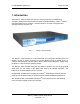
C-COM Satellite Systems Inc. Page 10 of 128 1. Introduction The iNetVu™ 7000 Controller is a one-box, one-touch solution for satellite autoacquisition. Designed to interface with a number of Satellite Modems, iNetVuTM VSATs, and DVB-S Receivers, the iNetVu™ 7000 Controller is an easily configurable and operated antenna controller unit. Fig. 1: iNetVu™ 7000 Controller The iNetVu™ 7000 Controller is a fully functionally and configurable straight off the box solution.
C-COM Satellite Systems Inc. Page 11 of 128 2. Specifications Dimensions: Weight: Operating Temperature: Elevation Output: Azimuth Output: Polarization Output: Universal AC Input: Motor Control Connector: Signal Input: GPS Connector: Rx Connector: PC Interface: Front Panel Interface: Width :17.1” x Depth:11.0” Height : 2.0” 9.9 lbs (4.5 kg) -20°C to +50°C 12VDC, 12 A (Max.) 12VDC, 12 A (Max.) 12VDC, 3 A (Max.) 90 – 264 VAC, 1.1 –2.
C-COM Satellite Systems Inc. Page 12 of 128 3. Physical Front Panel LEDs Manual Control Buttons LCD Screen Keypad Navigator RX IN LAN GPS Antenna Interfac Receive Signal from iNetVu Mobile Platform Network Interface RX OUT Serial port Serial Port Interface Fig.
C-COM Satellite Systems Inc. Page 13 of 128 4. Typical Connection Configuration The typical connection configuration for each service will be the same regardless of the Satellite Modem / VSAT. However, the configuration parameters for Satellite Modem / VSAT Communication will differ depending on service. See iNetVuTM System Manual for configuration procedures corresponding to the service used. iNetVu™ 7000 Controller User Manual Revision 1.
C-COM Satellite Systems Inc. 4.1. Page 14 of 128 Typical Network Interface Connection iNetVu™ Mobile Platform GPS Antenna TX RX SENSOR CABLE MOTOR CONTROL ! 90 - 264VAC RX Computer TX OUT Motor Control Cable Satellite Modem / VSAT Sensor Cable RG6 Coaxial Cable Network Cable Power Cable Fig. 3: iNetVu™ 7000 Controller Typical Connection Configuration iNetVu™ 7000 Controller User Manual Revision 1.
C-COM Satellite Systems Inc. 4.2. Page 15 of 128 Typical USB Communication Interface GPS Antenna TX RX SENSOR CABLE MOTOR CONTROL ! USB Cable Network Cable RX 90 - 264VAC TX OUT Satellite Modem / VSAT Motor Control Cable Sensor Cable RG6 Coaxial Cable Computer Network Cable Power Cable Fig. 4: USB Configuration Interface iNetVu™ 7000 Controller User Manual Revision 1.
C-COM Satellite Systems Inc. 4.3. Page 16 of 128 Typical Connection – PC Free GPS Antenna TX RX SENSOR CABLE MOTOR CONTROL Network Cable ! RX 90 - 264VAC Satellite Modem / VSAT Fig. 5: iNetVu™ 7000 Controller PC Free Connection Configuration Motor Control Cable Sensor Cable RG6 Coaxial Cable Network Cable Power Cable iNetVu™ 7000 Controller User Manual Revision 1.
C-COM Satellite Systems Inc. 4.4. Page 17 of 128 System Diagram with Splitter *Please Note: Using a splitter is optional. If the user does not wish to power the LNB from the Controller, a splitter must be used such that power is passed to the LNB from the VSAT Modem (or alternate power source). *If the splitter option is used, ensure the LNB Power is disabled in the 7000 Controller. (See section 7.2.2.
C-COM Satellite Systems Inc. Page 18 of 128 5. Installation The iNetVu™ 7000 Controller is shipped pre-configured and calibrated with the iNetVu™ Mobile Platform and service which you plan to use. Only configuration of the Satellite Modem / VSAT Communication parameters and the satellite you wish to find is required. 5.1. Rack Installation The iNetVu™ 7000 Controller includes attachable “ears” which make the iNetVu™ 7000 Controller configurable for rack-mounted installation.
C-COM Satellite Systems Inc. 5.3. Page 19 of 128 Existing iNetVu™ Mobile Platform Installation If you are replacing an existing iNetVu™ Series Controller with an iNetVu™ 7000 Controller, you will need to perform an Azimuth and Polarization Calibration and set the iNetVu™ Mobile Platform ID prior to searching for satellite.
C-COM Satellite Systems Inc. Page 20 of 128 3. After this is complete, go back to the Operations menu by pressing the “Exit” button to navigate backwards. 4. Advance to “PL_C” using the arrows and select the “Enter” key on the keypad. IMS will begin the Polarization Calibration Function. Verify that there are no obstructions that would impede a full Polarization sweep. Confirm the pot and zero factors when prompted and save. 5. After this is complete, navigate to the “Config” menu from the keypad.
C-COM Satellite Systems Inc. 6. iNetVuTM Front Panel Operation 6.1. LED Definition Fig. 7: iNetVu™ 7000 Controller Front Panel LED Panel POWER Solid light indicates power is ON. MOTOR Flashes when any of the three motors are instructed to move. COMM / LOCK Indicates Communication between Controller and Modem Slow blinking (2 sec. intervals) indicates no communication. Slow blinking (1 sec. intervals) indicates idle communication. Fast blinking (1/4 sec.
C-COM Satellite Systems Inc. 6.2. Page 22 of 128 Manual and Automatic Controls Button Operation Fig. 8: iNetVu™ 7000 Controller Front Panel Buttons How to Find Satellite Press “FIND SAT” Button. iNetVu™ Mobile Platform will automatically attempt to locate, lock, peak and enable the system onto the configured satellite. How to Stow the Antenna Press “STOP/STOW” Button, and hold for 2 seconds. iNetVu™ Mobile Platform will automatically re-center itself and lower into the stow position.
C-COM Satellite Systems Inc. 6.3. Page 23 of 128 LCD Screen and Navigator Keypad Operation Fig. 9: ↑ ← ↓ → ENTER EXIT iNetVu™ 7000 Controller LCD and Keypad Navigator Used to move the cursor position. Used to select a displayed function Used back out of a selection and return the display to the previous selection iNetVu™ 7000 Controller User Manual Revision 1.
C-COM Satellite Systems Inc. 6.4. Page 24 of 128 Front Panel Menu Navigation Tree The following is a tree consisting of a list of the menu options available with the LCD interface. iNetVuTM 7000 Controller LCD Menu MONITOR OPERATION MAIN EL AZ PL GPS CP DVB SAT MOD IP GW Fig.
C-COM Satellite Systems Inc. 6.5. Page 25 of 128 Opening Screen When powering the iNetVu™ 7000 Controller, the LCD will display the following during the initial boot-up sequence. iNetVu 7000 Control C-COM Fig. 11: 6.6. LCD Opening Screen Main Menu The iNetVu™ 7000 is ready for usage when the following is displayed on the LCD. There are Five (5) Main Menu items to select from: MONITOR, OPERATION, CONFIG, TEST, and INFO. MONITOR OPERATION CONFIG TEST INFO Fig.
C-COM Satellite Systems Inc. 6.6.1. Page 26 of 128 MONITOR This section describes briefly what each item and menu represents. For a more detailed explanation of each menu, see the configuration section of this manual. ( Section 6.6.3) MAIN EL AZ PL DVB SAT MOD Fig. 13: MAIN GPS CP IP GW Monitor Menu Displays real-time system status and receive signal.
C-COM Satellite Systems Inc. 6.6.1.1. Page 27 of 128 MAIN This branch menu displays the real-time Elevation, Azimuth, Polarization Angles, their respective limits (Up, Down, Stow), the RF Receive Signal, Signal Strength, and the System Status. 2 2 4 1 E-90.0 U D S A -45.7 S P-34.6 S 15U M140D ST VV 6 3 5 7 Fig. 14: “MAIN” (Main) Display 1 – Elevation Angle and Limit Indicators Ka66/740/950/980 Mobile Platform Range: 1200/1800 Mobile Platform Range: 1.2m Flyaway Antenna -90.0 to 65+ -90.
C-COM Satellite Systems Inc. S Polarization Stow Limit has been reached. Mobile Platform should be physically centered on the Polarization axis. iNetVu™ 7000 Controller User Manual Revision 1.
C-COM Satellite Systems Inc. Page 29 of 128 4 – System Status (status meanings explained in the software section of this report) AC AT CC DT EC II LK MM PC PK PS SG SR ST Azimuth Calibration ACP Testing Compass Calibration Dish Testing Elevation Calibration Idle Locked on Satellite Manual Movement Polarization Calibration Peaking Positioning Stowing Searching Stowed 5 – Receive RF Signal Receive RF Signal as measured from the LNB.
C-COM Satellite Systems Inc. 6.6.1.2. Page 30 of 128 EL Displays real-time current drawn and speed settings for the elevation motor, as well as real-time elevation angle and limits, offset, window size, and Elevation adjustment gap. 1 2 3 5 E0.0 D U S S: 5 AD: 3 I/S:0-6 U D O: 31 4 Fig. 15: “EL” (Elevation) Display 1 – Real-Time Elevation Angle E (Elevation) The number value after the “E” represents the real time elevation angle.
C-COM Satellite Systems Inc. 6.6.1.3. Page 31 of 128 AZ Displays real-time current drawn and speed settings for the azimuth motor, as well as real-time azimuth angle and limits, search window size, zero and pot factor. 1 2 3 4 A0.0 S W: 60 Fig. 16: I/S:0-6 L R ZF: 346.1-0.6604 “EL” (Elevation) Display 1 – Real-Time Azimuth Angle A (Azimuth) – Real time Azimuth angle reading, down to the tenth of a decimal.
C-COM Satellite Systems Inc. 6.6.1.4. Page 32 of 128 PL Displays real-time current drawn and speed settings for the polarization motor, as well as real-time polarization angle and limits, offset, zero and pot factor. 1 2 3 4 P0.0 S O0 Fig. 17: I/S:0.0-7 L R ZF: 346.1-0.6604 “PL” (Polarization) Display 1 – Real-Time Polarization Angle P (Polarization) – Indicates the real time polarization angle of the iNetVuTM Antenna.
C-COM Satellite Systems Inc. 6.6.1.5. Page 33 of 128 GPS Displays GPS Status and current GPS Heading. 2 3 1 GPS: V V0 H338 LA: 45.4N LG: 75.6W 4 Fig. 18: “GPS” (GPS) Display 1 – GPS Status V F O GPS Status is Valid GPS Status has Failed GPS Coordinates have been overridden 2 – GPS Velocity 3 – GPS Heading 4 – GPS Coordinates LA LG Current Latitude Coordinate rounded to one decimal place in degree format. Current Longitude Coordinate rounded to one decimal place in degree format.
C-COM Satellite Systems Inc. 6.6.1.6. Page 34 of 128 CP Displays Compass Status, Compass Heading and the Elevation at which the Compass is read. 2 1 3 CP: O H :159 V : 0-90-180-270 CP_EL : 35 4 Fig.
C-COM Satellite Systems Inc. 6.6.1.7. Page 35 of 128 DVB Displays the Target Satellite Transponder Frequency, Symbol Rate, and Code Rate in order to give the DVB Tuner a lock status once pointed towards satellite. 3 2 4 T0 1310 T0 0990 1 5 30000 30000 DVB-7/8 DD DVB-7/8 DD 6 9 10 8 7 Fig.
C-COM Satellite Systems Inc. 6.6.1.8. Page 36 of 128 SAT Displays the Target Satellite and its calculated coordinates based on the GPS Heading, Compass Reading, and orbital slot of the desired Satellite. 2 1 93.0W R:8WD E64.5 A145.2 P40 3 5 4 Fig. 21: “SAT” (Satellite) Display 1 – Target Satellite (i.e. 93.0W represents satellite at 93º longitude west) 2 – Target Reference Satellite D - Reference Satellite Search Mode Disabled. E – Reference Satellite Search Mode Enabled.
C-COM Satellite Systems Inc. Page 37 of 128 6.6.1.10. IP Displays the IP Address of the iNetVu™ 7000 Controller (C_IP) and the IP Address of the VSAT Modem (M_IP). 1 C_IP : 192.168.0.2 M_IP: 192.168.0.1 2 Fig. 22: “IP” (IP) Display 1 – iNetVu™ 7000 Controller’s IP Address (Default: 192.168.0.2) 2 – VSAT Modems IP Address (User Defined) 6.6.1.11. GW Displays the Gateway Parameters of the iNetVu™ 7000 Controller 1 S_IP : 255.255.0.0 G_IP: 192.168.0.1 2 Fig.
C-COM Satellite Systems Inc. 6.6.2. Page 38 of 128 OPERATION 2 1 3 4 FIND AZ_C STOW PL_C Tx_E CP_C Tx_D 7 5 6 Fig. 24: FIND STOW Operation Menu (Find Satellite) Performs automatic satellite acquisition. Stows the antenna Tx_E (Transmitter Enable) Enables the transmitter after locking onto the designated satellite. Tx_D (Transmitter Disable) Disables the transmitter after locking onto the designated satellite. AZ_C (Azimuth Calibration) Performs a complete Azimuth Calibration.
C-COM Satellite Systems Inc. Page 39 of 128 4 –Transmitter Disable Disables the Transmitter once locked onto satellite. 5 –Azimuth Calibration Performs a complete Azimuth Calibration. Antenna will completely rotate counter-clockwise to the physical limit and temporarily record the A/D value from the Potentiometer. Antenna will completely rotate clockwise to the physical limit and temporarily record the A/D value from the Potentiometer.
C-COM Satellite Systems Inc. Page 40 of 128 This end faces South North - 354 West - 265 South - 176 East - 87 This end faces North Fig. 25: Compass Orientation and Approximate Values The Antenna will now rotate in 90 intervals and attempt to calibrate the compass. A message prompt will appear to notify you that the Compass Calibration has been completed successfully or not. iNetVu™ 7000 Controller User Manual Revision 1.
C-COM Satellite Systems Inc. 6.6.3. Page 41 of 128 CONFIG This Menu will allow the user to configure all components of the iNetVuTM System. A description of each menu and their purpose is outlined below. This section explains the different components of the configuration menu, and what each component means. A step-by-step procedure of how to configure the system is explained in the appendices. Please refer to the section in the appendices corresponding to the service you may be using.
C-COM Satellite Systems Inc. Page 42 of 128 subnet IP address, as well as the controller gateway IP address. Configuration screen of the controller IP address, and the VSAT modem’s IP address. Service Configuration screen, allows for the type of service selection and means of communication. IP SR 6.6.3.1. SAT Allows for the Configuration of the target satellite and the satellite polarization offset.
C-COM Satellite Systems Inc. 6.6.3.2. Page 43 of 128 MOD 2 1 3 0990 30000 TR :HV H :W 4 1 – Configured Satellite Modem Receive Frequency in MHz with no decimals. 2 – Configured Satellite Modem Symbol Rate in Ksps. 3 – Transmit and Receive Polarization.
C-COM Satellite Systems Inc. 6.6.3.3. Page 44 of 128 DVB Allows the configuration of the Target Satellite Transponder Frequency, Symbol Rate, and Code Rate in order to give the DVB Tuner a lock status once pointed towards satellite. 2 3 1 4 T0 T0 1310 0990 30000 30000 DB-7/8 DB-7/8 9 DD DD 10 5 8 6 7 Fig.
C-COM Satellite Systems Inc. Page 45 of 128 9 - LNB Power (Target Satellite) In cases where the LNB requires more power then the modem can provide, or if the user would like to power LNB from the controller, or if the user would like to find satellite without the use of a modem, this option allows for power from the controller to be supplied to the LNB through the RX IN cable from the controller to the platform itself. DD – will disable this option, and provide power to the LNB straight from the modem.
C-COM Satellite Systems Inc. 6.6.3.4. Page 46 of 128 EL The EL menu allows for the Configuration of the elevation axis. Options include configuring the elevation offset, the satellite search window, the elevation adjustment gap, the mechanical elevation limits, the slow speed, and the current limits. 2 3 1 4 5 6 O: 31 S: 6 Fig. 30: W:05 A:03 L:EEE I:12-05 “EL” (Elevation Configuration) Display 1 – Elevation Offset The Elevation Offset is specific to each type of platform.
C-COM Satellite Systems Inc. Page 47 of 128 3 - Advanced Search Elevation Gap With a configurable range of (2º-20º) this parameter is used to determine the small incremental adjustments required for a more accurate satellite search. Decreasing this value will add accuracy to the Search Window, but will increase the search time. This value is used while searching on an inclined surface. For instance A: 03 means the elevation angle will adjust if 3º gap from the calculated angle.
C-COM Satellite Systems Inc. 6.6.3.5. Page 48 of 128 AZ The AZ menu allows configuration of the Azimuth axis, including pot zero, pot factor, stow limit, azimuth search window size, slow speed movements, and current limits at high and slow speeds. 2 3 1 4 6 Z: 346.9 W: 60 F:0.6604 S: 6 E I:08-05 5 Fig.
C-COM Satellite Systems Inc. Fig. 33: Page 49 of 128 Azimuth Coverage of search window The default Azimuth (Horizontal) range is 60° on each side of the Target Point. Increasing the size of the Search Window will increase the ability to find the desired Satellite, although increasing the Search Window will lengthen the search time. 5 –Speed Setting S The user may configure the slow speed of the azimuth movement. The slow speed is a basis for the satellite searching procedure.
C-COM Satellite Systems Inc. 6.6.3.6. Page 50 of 128 PL The PL menu allows for the configuration of the polarization axis. Options include the setting of the pot zero, and the pot factor, as well as the skew adjustment and stow limit functionality, the polarization offset, slow speed, and current limits for fast and slow speeds. 2 3 1 4 6 Z: 346.9 O: +0 F: 0.6604 S: 7 DE I: 1.5-1.
C-COM Satellite Systems Inc. Page 51 of 128 4 - Polarization Offset By default this polarization-offset value is set to +0°. If there happens to be a requirement for a polarization offset, the user may manually enter this value in this area. 5 –Speed Setting S The user may configure the slow speed of the polarization movement. The slow speed is a basis for the satellite searching procedure. See appendix 3 for details.
C-COM Satellite Systems Inc. 6.6.3.7. Page 52 of 128 G&C Allows for the Configuration of the GPS parameters and settings, as well as the Compass parameters and settings. 2 1 3 G :O C :O 45.41N 75.62W H :159 E : 62 O:+44 4 7 6 Fig. 34: 5 “G&C (GPS and Compass) Configuration 1 – GPS Status Configuration N O Use Coordinates from GPS Antenna Override GPS and use the coordinates entered (2) and (3). Enables the GPS coordinates to be manually overridden.
C-COM Satellite Systems Inc. Page 53 of 128 6 – Elevation of Compass Reading Number of degrees that the Antenna requires to be elevated to ensure that the compass is level and is able to acquire an accurate compass reading (see appendix 3 for default values). iNetVu™ 7000 Controller User Manual Revision 1.
C-COM Satellite Systems Inc. 6.6.3.8. Page 54 of 128 C&P This menu allows for the configuration of the controller input settings as well as the platform type and serial number. 2 1 3 7 RF : N- 00 S&P :SS MP :D BP : E DH :D A74-2000 6 5 4 Fig. 35: “CP” Compass Display 1 – RF Signal Status and Threshold (Threshold should be set only if RF is overridden) N O Normal Receive, the Rx Signal is taken from the Rx IN input of the DVB tuner.
C-COM Satellite Systems Inc. Page 55 of 128 4- Beep This option allows for enabling and disabling the Beeping sound when navigating the LCD screen through the front panel keypad. E – Beep Enabled, a beeping sound will occur upon navigation the LCD Interface. D – Beep Disabled, the sound will be completely removed.
C-COM Satellite Systems Inc. 6.6.3.9. Page 56 of 128 RT This menu will allow the user to configure a router (if necessary) IP address and the Domain Name Server (DNS) IP address. Note: This menu is still under development, and is currently not functional) 1 R_IP : 192.168.0.2 D_IP: 192.168.0.1 2 Fig. 37: “RT” (Router and DNS) Configuration 1 – Router IP address 2 – DNS IP address 6.6.3.10.
C-COM Satellite Systems Inc. Page 57 of 128 6.6.3.11. IP This menu will allow the user to configure the controller IP address, as well as the Modem IP address. 1 C_IP : 192.168.0.3 M_IP: 192.168.0.1 2 Fig. 39: “IP” Configuration 1 – iNetVuTM 7000 Controller’s IP Address 2 – Modem IP Address (Default: 192.168.0.1) 6.6.3.12. SR This menu will allow the user to configure the controller to the service used for 2-way satellite communication. 2 3 1 ID_TELT C :dBUG-19200 PWD :P@55w0rd! 4 Fig.
C-COM Satellite Systems Inc. Page 58 of 128 2 – Modem Communication Interface TELT - Telnet Interface COM - Console Port Interface HTTP - HTTP Interface NA - No modem interface applicable, this option is generally selected with the stand-alone service. Locking and peaking onto satellite is based on the DVB Signal and not on the modem SNR value. 3 – Debugging Interface Used by C-COM Satellite Systems Inc. for internal testing.
C-COM Satellite Systems Inc. 6.6.4. Page 59 of 128 TEST E&A&P A_ACP CP DPLY M_ACP Fig. 41: E&A&P CP DPLY DPLY_C S_ACP Test Menu Will allow for Demo Testing on all axes (elevation, azimuth, and polarization) for a user specified angle range. Tests the compass’ heading and accuracy by rotating the antenna at 90° intervals and comparing the compass readings with the actual antenna’s movement. Deploys the antenna to a user specified azimuth, elevation, and polarization position.
C-COM Satellite Systems Inc. 6.6.4.1. Page 60 of 128 E&A&P 1 2 E +20:70:7 A-180: 180:7 DD: D P-60: 60:7 TST 5 3 4 1 – Elevation Movement Allows the user to set the start and stop angle of the elevation axis, as well as set the specific speed for elevation movement. (E +20:70:7 –implies from angle 20 to 70 at speed 7) 2 – Polarization Movement Allows the user to set the start and stop angle of the polarization axis, as well as set the specific speed for polarization movement.
C-COM Satellite Systems Inc. 6.6.4.2. Page 61 of 128 CP 2 1 3 CP:V H:0 0-90-180-270 CP_EL 4 1 – Compass Status V – Valid O – Override F - Failed 2 – Compass Heading 3 – Compass Reading Angle Elevation Angle at which compass is read 4 – Compass Accuracy Readings Tests the compass’ heading and accuracy by rotating the antenna at 90 intervals and comparing the compass readings with the actual antenna’s movement. i. ii. iii. iv.
C-COM Satellite Systems Inc. 6.6.4.3. Page 62 of 128 DPLY 2 1 E: +20 A +180 P+60 DPLY 3 4 1 – Elevation Movement User-defined elevation angle of deploy 2 – Polarization Movement User-defined polarization angle of deploy 3 – Azimuth Movement User-defined azimuth angle of deploy 4 – Deploy Automatically moves antenna to the manually entered Elevation, Azimuth and Polarization angles. iNetVu™ 7000 Controller User Manual Revision 1.
C-COM Satellite Systems Inc. 6.6.4.4. Page 63 of 128 DPLY_C 2 1 E: +20 A +180 P+60 CP T 3 4 1 – Elevation Movement User-defined target elevation angle of for compass reading 2 – Polarization Movement User-defined target polarization angle for compass reading 3 – Azimuth Movement User-defined target azimuth angle for compass reading 4 – Check Compass at specified target point.
C-COM Satellite Systems Inc. 6.6.5. Page 64 of 128 INFO Displays information regarding the iNetVu™ 7000 Controller’s firmware and software versions installed, the Mobile Platform it is configured to, and also any Error Codes detected. CC1 CC2 DVB MOD ERR Fig. 42: “INFO” (Information) Display CC2 Contains information pertaining to the iNetVu TM 7000 Controller hardware version, software version, firmware version, boot loader version, MAC address, and configuration ID.
C-COM Satellite Systems Inc. 6.6.5.1. Page 65 of 128 CC1 This branch menu displays the controller ID, Hardware Version, Firmware, and Boot loader Version 2 2 3 1 ID: 9999 SQ_T: 31 FBV:7.0.0.1—7.0.0.1 HW:0 4 Fig. 43: “CC1” (Controller Info 1) Display 1 – Controller ID Number The iNetVu™ Controller Serial Number is located on the base of the controller. It is the last 4 digits of the Serial Number.
C-COM Satellite Systems Inc. 6.6.5.3. Page 66 of 128 DVB This branch menu displays the controller DVB Module Type. 1 DVB-S-0 Fig. 45: “DVB” (DVB Module) Display 1 – The DVB Module currently embedded into the iNetVuTM 7000 Controller. 6.6.5.4. MOD This branch menu displays the VSAT Modems ID, Serial Number, and software version number. 2 1 SN: 3863 V: 6.0.9.0 S: 2 3 Fig.
C-COM Satellite Systems Inc. Page 67 of 128 7. iNetVuTM 7000 Software The iNetVu™ Mobile Software plays an integral role in connecting you and iNetVu™ Mobile System. It has the ability to communicate with the Satellite Modem, automatically find and lock onto a satellite and stow the antenna when completed.
C-COM Satellite Systems Inc. 7.1. Page 68 of 128 Operation Modes iNetVu™ 7000 Mobile Software currently offers only one mode of operation for its users. iNetVu™ 7000 Controller User Manual Revision 1.
C-COM Satellite Systems Inc. 7.2. Page 69 of 128 Navigating Menus To navigate the iNetVu™ Mobile Software, right-click the iNetVu™ swirl icon located in the System Tray. There are 4 options available: Advanced Controls Maintenance About Exit iNetVu™ 7000 Controller User Manual Revision 1.
C-COM Satellite Systems Inc. 7.2.1. Page 70 of 128 Advanced Controls The Advanced Controls menu allows users to monitor system parameters and manually move the antenna, as well as conduct automatic processes and functions. Improper use of Advanced Controls menu can render the iNetVu™ Mobile System inoperable and may be in violation of FCC regulations. The user can halt any operation at any time by clicking STOP button located in the Automatic Controls. Fig.
C-COM Satellite Systems Inc. Page 71 of 128 Signal Strength A real-time Signal Quality Factor (SQF). A value obtained from the Satellite Modem when locked onto a signal. Using a red/yellow/green color-coated system, it denotes the strength of the received signal from the current satellite. Should the Signal Strength be lower than 29 when locked on satellite, click Find Satellite again to re-acquire the signal. Fig.
C-COM Satellite Systems Inc. Page 72 of 128 Find Satellite Automatically finds and locks onto the satellite signal by communicating with the Satellite Modem and using the GPS coordinates, the compass heading, and internal parameters of the Satellite Modem. Typically, it takes approximately 3-5 minutes to find satellite. If the Antenna is already pointed on the satellite, clicking Find Satellite will repeak the Antenna onto the signal.
C-COM Satellite Systems Inc. Page 73 of 128 Angle and Limit Switch Indicators Displays real-time angles and Limit Switch status Elevation UP Limit Indicator Elevation Angle Elevation DOWN Limit Indicator Elevation STOW Limit Indicator Azimuth Angle Azimuth STOW Limit Indicator Polarization STOW Limit Indicator Polarization Angle Fig.
C-COM Satellite Systems Inc. Page 74 of 128 Manual Movement Elevation Up / Elevation Down Azimuth Left/ Azimuth Right Polarization Counter-Clockwise / Polarization Clockwise Using the Duration and Speed parameters, the Manual Movement Buttons allow you to move the antenna in six (6) directions. For the correct point of reference for the directional movements, you must be facing the Mobile Platform’s Reflector. Face this direction for correct Azimuth and Polarization Orientation Fig.
C-COM Satellite Systems Inc. Page 75 of 128 Enable/Disable ACP Enables/Disables the ACP (Automatic Cross-Pol Testing), and M-ACP (Manual Cross-Pol Testing) Fig. 56: ACP Option Selection To Enable ACP, select “AUTO” or “MANUAL” from the ACP drop down list and click on the ‘Enable/Disable ACP’ Button to initiate. To Stop ACP testing, select “STOP” from the ACP drop down list, and click on the Enable/Disable ACP Button to initiate.
C-COM Satellite Systems Inc. Page 76 of 128 DVB Signal (0-300) DVB Signal received from the DVB Tuner. RF Signal (30-75) Displays the real time RF Signal throughout the acquisition process. RF Threshold (30-75) Used in RF mode search for determining proper satellite frequency. Antenna Latitude/Longitude GPS Coordinates acquired from the GPS Antenna or manually overridden values. Antenna Altitude Altitude of antenna above sea level based on the GPS Antenna.
C-COM Satellite Systems Inc. Page 77 of 128 Target Elevation Calculated Elevation Angle that the Antenna must point in order to locate the desired Satellite. Target Real Azimuth Calculated Azimuth Angle that the Antenna must point in order to locate the desired Satellite in reference to True North. Target Antenna Azimuth Calculated Azimuth Angle that the Antenna must point in order to locate the desired Satellite in reference to the Mobile Platform’s center position.
C-COM Satellite Systems Inc. Page 78 of 128 EL Motor Current Current drawn for Elevation Motor (in Amperes) AZ Motor Current Current drawn for Azimuth Motor (in Amperes) PL Motor Current Current drawn for Polarization Motor (in Amperes) Message Panel Displays real-time status updates, system messages, and error codes. Fig. 59: Message Panel Status Panel The Status Panel describes system operations that are either imminent, taking place, or the current status of that component.
C-COM Satellite Systems Inc. Page 79 of 128 Should the entire Status Panel flash “RED” and “YELLOW”, a communication failure between the PC and the iNetVu™ Controller has occurred. Ensure that the Controller is powered, and that all USB drivers and cables (USB or Serial) are installed properly. System Status Displays current system environment System Running Software is currently booting. System Idle No operations are currently being performed.
C-COM Satellite Systems Inc. Page 80 of 128 Satellite Modem Communication Status Indicates the Transmitter status and displays any issues in communication with the Satellite Modem Checking Modem Verifying Satellite Modem’s current status Transmitter Enabled Indicates that the transmitter has been enabled. Transmitter Disabled Indicates that the transmitter has not been enabled. Transmitter Standby Transmitter becomes idle during the ACP Test.
C-COM Satellite Systems Inc. Page 81 of 128 Antenna Status Displays any relevant information regarding the Limit Switches and Potentiometers and/or Inclinometer. Antenna Normal Limit Switches are ON/OFF in the correct relation to the Elevation, Azimuth and Polarization Angles. Antenna Failed Limit Switches are NOT ON/OFF in the correct relation to the Elevation, Azimuth and Polarization Angles. Antenna Unknown Mobile Platform cannot be found.
C-COM Satellite Systems Inc. 7.2.2. Page 82 of 128 Maintenance The Maintenance menu allows users to configure the communication medium between the Satellite Modem and iNetVu™ Mobile Software, iNetVu™ Controller and iNetVu™ Mobile Software, as well as various System parameters for optimal performance. The Maintenance menu allows users to set the Satellite’s name and orbital slot, conduct maintenance tests/processes, override parameters, and run a system diagnosis check.
C-COM Satellite Systems Inc. 7.2.2.1. Page 83 of 128 Satellite Parameters Fig. 62: Maintenance – Satellite Parameters Sat Lon Orbital slot / Longitude of the desired Satellite. The Find Satellite command will use this value when attempting to find and lock onto a satellite signal.
C-COM Satellite Systems Inc. Page 84 of 128 7000 Controller Power Output Range Option Capabilities: 13, 14, 18, 19, 20, 21 V @ 500mA (max) If the user chooses to power the LNB from the controller, he/she should verify the power/voltage range requirements of the LNB in use, and configure the iNetVuTM 7000 Controller according to those power/voltage requirements. TR No. (Transponder Number) There are Six (6) Transponder values in the 7000 Controller for each satellite.
C-COM Satellite Systems Inc. 7.2.2.2. Page 85 of 128 Reference Satellite Parameters The reference satellite option is useful when the user cannot find a DVB transponder on the desired target satellite. The user may select a reference satellite with a known DVB Transponder. The iNetVuTM System will lock onto the reference satellite, and then pivot from that point to the desired target satellite, and peak on the modem signal. Fig.
C-COM Satellite Systems Inc. Page 86 of 128 TR No. (Transponder Number) There are Six (6) Transponder values in the 7000 Controller for each satellite. Transponder 0-2 (TR0_H – TR0_H) are horizontal receive Transponder 3-5 (TR3_V –TR5_V) are vertical receive. The user may override the default values saved in the controller with his/her transponder information (frequency, symbol rate, FEC rate) for the reference satellite.
C-COM Satellite Systems Inc. 7.2.2.3. Page 87 of 128 Modem Parameters Fig. 65: Maintenance – Modem Parameters Type The user must select the service in use from this drop down menu for proper modem to controller connectivity. The services currently provided are: iDirect Hughes Viasat NA – Stand Alone DVB transponder finder INF (Interface) The user may select the interface used for modem to controller communication establishment.
C-COM Satellite Systems Inc. Page 88 of 128 Tx-Pol Transmit Polarization set in the satellite modem Rx-Pol Receive Polarization set in the satellite modem Note: For Hughes Net service the Modem Frequency, Symbol Rate, Receive and Transmit Polarization must match those set in the Satellite Modem. Hemisphere Hemisphere the modem is operating from. For instance, North American operating modems would be set to “W”, representing western hemisphere. This parameter is mainly used for Hughes Net service.
C-COM Satellite Systems Inc. 7.2.2.4. Page 89 of 128 Search Parameters Fig. 66: Maintenance – Search Parameters EL Window / AZ Window The Search Window is the area of the sky which the iNetVu™ Mobile System will search for the desired Satellite. It uses a rectangular window and searches for the Satellite using smaller concentric windows until the desired Satellite is found.
C-COM Satellite Systems Inc. Page 90 of 128 Search on RF This option will allow the user to base satellite searching and peaking strictly on RF instead of DVB. This method of searching could be used when the user is having a hard time finding the transponder data for a specific satellite, or if no transponder data exists. RF Threshold Used by the iNetVu™ Mobile Software to begin a signal optimization process for peaking on a Satellite signal after initially locating it.
C-COM Satellite Systems Inc. 7.2.2.5. Page 91 of 128 GPS and Compass Fig. 68: Maintenance – GPS and Compass Parameters GPS Lat This field represents the Latitudinal GPS coordinates of the iNetVuTM system. GPS Lon This field represents the Longitudinal GPS coordinates of the iNetVuTM system. Override GPS Checkbox Enables the GPS coordinates to be manually overridden.
C-COM Satellite Systems Inc. Page 92 of 128 After enabling Override, you may enter the vehicle’s direction as indicated on your alternate compass. Keep in mind that the base of the iNetVu™ Mobile Platform is oriented to the rear of your vehicle. When taking the direction on the alternate compass, take the direction of your reading while facing the front of the vehicle, and use this orientation for the Vehicle Direction field.
C-COM Satellite Systems Inc. Page 93 of 128 DIR (Direction) The direction the front of the Mobile Platform is rotated in reference to True North. In order to override the compass, the user must know where true north is located to enter the direction. Offset The number of degrees the Mobile Platform is rotated in reference to True North. iNetVu™ 7000 Controller User Manual Revision 1.
C-COM Satellite Systems Inc. 7.2.2.6. Page 94 of 128 Controller Parameters This sub-section contains data concerning the relevant IP addresses of the iNetVuTM 7000 Controller. Fig. 71: Maintenance – Controller Parameters ID This ID field is the Controller ID number located on the bottom portion of the controller. The ID is the last four digits of the controller serial number. IP The IP address assigned to the iNetVuTM 7000 Controller. GW The Gateway IP address used by the iNetVuTM 7000 Controller.
C-COM Satellite Systems Inc. Page 95 of 128 SPEED (bps) The user may define the bit rate of the serial communication interface. BEEP This checkbox is used to either enable or disable the beeping noise when navigating the LCD interface on the iNetVuTM 7000 Controller. UPLOAD The user may choose to upload either 1 hour, 2 hours, or ALL (maximum of 12 hours) of the recorded log information from the controller to the PC.
C-COM Satellite Systems Inc. 7.2.2.7. Page 96 of 128 Platform Parameters Maintenance – Platform Parameters Type The user is capable of configuring the platform in use.
C-COM Satellite Systems Inc. 7.2.2.8. Page 97 of 128 Elevation Parameters The Elevation menu allows for the configuration of the elevation axis. Options include the elevation offset, as well as the axis limit functionality, slow speed setting, and current limits for fast and slow speeds. Fig. 73: Maintenance - Elevation Parameters Offset The Elevation Offset is specific to each type of platform.
C-COM Satellite Systems Inc. Page 98 of 128 @ speed 6 and 9. See appendix 3, table 5 for the default current limits for all iNetVuTM Mobile Platforms. • Current Limit 8 – 90% of Current Limit 9 • Current Limit 7 – 80% of Current Limit 9 • Current Limit 5 – 90% of Current Limit 6 • Current Limit 4 – 80% of Current Limit 6 iNetVu™ 7000 Controller User Manual Revision 1.
C-COM Satellite Systems Inc. 7.2.2.9. Page 99 of 128 Azimuth Parameters The Azimuth menu allows for the configuration of the azimuth axis. Options include the setting of the pot zero, and the pot factor, as well as the axis limit functionality, the slow speed setting, and current limits for fast and slow speeds. Fig. 75: Maintenance - Azimuth Parameters Slow Speed The iNetVuTM software basis the default azimuth motor slow speed on the platform size and type. See appendix 3, table 5 for details.
C-COM Satellite Systems Inc. Page 100 of 128 AZ Pot Zero AZ Pot Zero is an A/D value from the potentiometer calculated upon azimuth calibration which physically determines where the iNetVu™ Mobile Software places Azimuth Angle 0°. The AZ Pot Zero may vary approximately +15% from the Default values (see appendix 3, table 5). The user may edit these values through this menu, however any changes may result in failure to recognize the correct 0° angle.
C-COM Satellite Systems Inc. Page 101 of 128 7.2.2.10. Polarization Parameters The Polarization menu allows for the configuration of the polarization axis. Options include the setting of the pot zero, and the pot factor, as well as the skew adjustment and stow limit functionality, the polarization offset, slow speed, and current limits for fast and slow speeds. Fig.
C-COM Satellite Systems Inc. Page 102 of 128 PL Pot Zero PL Pot Zero is an A/D value from the potentiometer that physically determines where the iNetVu™ Mobile Software places Polarization Angle 0°. The PL Pot Zero may vary approximately +15% from the Default values (see appendix 3). The PL Pot Zero is calculated during the Polarization Calibration process. The user may edit these values through this window, however any changes may result in failure to recognize the correct 0° angle.
C-COM Satellite Systems Inc. Page 103 of 128 7.2.2.11. Maintenance Menu Buttons The following buttons are available in the maintenance menu for multiple purposes including, ease of use, troubleshooting, and calibration. Calibrate AZ Performs automated Polarization Calibration process. i. ii. iii. iv. v. vi. Antenna will completely rotate counter-clockwise to the physical limit and temporarily record the A/D value from the Potentiometer.
C-COM Satellite Systems Inc. Page 104 of 128 ii. Orient the Mobile Platform as depicted in the following figure. It is recommended that you use an external compass to be as accurate with the orientation as possible. This end faces South North - 354 West - 265 South - 176 East - 87 This end faces North Fig. 77: Compass Orientation and Approximate Values iii. The Antenna will now rotate in 90 intervals and attempt to calibrate the compass. iv.
C-COM Satellite Systems Inc. Page 105 of 128 Demo / Test Opens System Test and Demo menu screen Log File Automatically opens the iNetVu Data Log File in Notepad. Load Firmware Loads the iNetVu_Box.s19 firmware file into iNetVu™ Controller from the iNetVu program folder. The update process is displayed on screen and will notify the user when the process is complete. The controller will be unavailable during this time. Write EPROM Sends and writes ALL the parameter’s to the iNetVu™ Controller’s EPROM.
C-COM Satellite Systems Inc. Page 106 of 128 7.2.2.12. Maintenance Test Screen Used for system tests, trouble-shooting, and for demonstrating the iNetVu™ Mobile System. Fig.
C-COM Satellite Systems Inc. Page 107 of 128 Test Compass Positions Antenna to a level Elevation angle and updates compass heading.
C-COM Satellite Systems Inc. 7.2.3. Page 108 of 128 About Displays information to the user about various sub-system components, as well as contact information for support and feedback. Fig. 79: About Menu Software Version iNetVu™ Mobile Software version Build ID Date of software release Work Mode Current Operation Mode iNetVu™ 7000 Controller User Manual Revision 1.
C-COM Satellite Systems Inc. Page 109 of 128 Controller Firmware iNetVu™ Controller’s firmware version. For compatibility purposes, Controllers are preconfigured with the appropriate firmware for the accompanied software version. Service/ ID iNetVu™ Controller Serial Number ID. This field is supported for iNetVu™ Controller Firmware 4.2 and higher. Interface This field represents the means of communication between the iNetVuTM software, and the 7000 Controller.
C-COM Satellite Systems Inc. Modem Type Modem Type, corresponding to the service provided. Firmware Satellite Modem’s firmware version. ID Satellite Modem’s Hardware ID or Serial Number Interface Modem Interface to the iNetVuTM 7000 Controller. iNetVu™ 7000 Controller User Manual Revision 1.
C-COM Satellite Systems Inc. Page 111 of 128 8. iNetVuTM 7000 Controller Web Interface Another method of communicating remotely with the 7000 Controller is through the web interface. It has the ability to communicate with the Satellite Modem, automatically find and lock onto a satellite and stow the antenna when completed.
C-COM Satellite Systems Inc. 8.1. Page 112 of 128 Navigating Menus To view the web interface, type in the IP address of the 7000 Controller in the web browser. There are 4 options available: Login (default password: “password”) Controls Maintenance About Firmware Update Satellite Table Update To reset the password, click on “Reset my password”, and enter “123456789” for the reset ID. iNetVu™ 7000 Controller User Manual Revision 1.
C-COM Satellite Systems Inc. 8.2. Page 113 of 128 Controls Similar to the iNetVuTM 7000 Software Controls Menu, the Web Interface Controls Screen allows the user to monitor system operations, and perform automatic as well as manual system functions. (See Section 7.2.1 for more details) Fig. 80: Web Interface - Controls Screen iNetVu™ 7000 Controller User Manual Revision 1.
C-COM Satellite Systems Inc. 8.3. Page 114 of 128 Maintenance The Maintenance menu allows users to configure the communication medium between the Satellite Modem and iNetVu™ 7000 Web Interface, iNetVu™ Controller and iNetVu™ Web Interface, as well as various System parameters for optimal performance. The Maintenance menu allows users to set the Satellite’s name and orbital slot, conduct maintenance tests/processes, override parameters, and run a system diagnosis check.
C-COM Satellite Systems Inc. 8.4. Page 115 of 128 About Displays information to the user about various sub-system components, as well as contact information for support and feedback. (See Section 7.2.3 for more detail on subcomponents) Fig. 82: Web Interface - About Screen iNetVu™ 7000 Controller User Manual Revision 1.
C-COM Satellite Systems Inc. 8.5. Page 116 of 128 Firmware/Satellite Table Update To access the firmware update, and satellite table update screen, perform the following steps: 1. After establishing a proper network connection between the controller and the PC, press the “reset” button on the 7000 Controller, and hold the “↑” and “↓” buttons on the front panel at the same time until you read “Firmware/Sat update” on the LCD screen. 2.
C-COM Satellite Systems Inc. 8.5.1. Page 117 of 128 Firmware Update To update the controller firmware click on the “Update Firmware” link on the left panel of the firmware/satellite table update web page. The following screen should appear: Fig. 84: Firmware Update Screen To update the firmware via web page: 1. Browse for the proper firmware (.s19) file from your local disk drive. 2. Click on the “Upgrade” button. 3.
C-COM Satellite Systems Inc. 8.5.2. Page 118 of 128 Satellite Table Update In order to update the table containing the satellite transponder data, the iNetVu7000_SatParam.txt file must be manually changed. For example, If a user wishes to add a transponder to satellite 91W, he/she would locate satellite 91W in the table, and replace one of the transponders with the new transponder data. Save the file once the changes have been made. To upload the changed table to the controller: 1.
C-COM Satellite Systems Inc. Page 119 of 128 9. Controller Connectivity In order to interface directly with the iNetVu™ 7000 Controller, a Network Interface and a Web Interface are available. The Network/Web Interface allows the user to operate the automatic functions such as Finding Satellite, Stowing the Antenna, and Stopping Operations, as well as monitoring System Status, real-time Motor Currents, and Signal Strength.
C-COM Satellite Systems Inc. 9.1. Page 120 of 128 Network Configuration Example *See appendix 3 for router configuration Direct Connection to PC: Straight / Crossover Network Cable iNetVu 7000 Controller Computer IP Address: 192.168.0.2 Subnet Mask: 255.255.255.0 Gateway: 192.168.0.1 IP Address: 192.168.0.3 Subnet Mask: 255.255.255.0 Gateway: 192.168.0.2 Fig.
C-COM Satellite Systems Inc. 9.2. Page 121 of 128 How to Set Network Configurations on your PC 1. Open Network Connections, right-click your network card, and select Properties. 2. Select Internet Protocol (TCP/IP) and click Properties. 3. Direct Network Connection: Set your PC to the same subnet as the iNetVu™ 7000 Controller, and the Default Gateway to the iNetVu™ 7000 Controller. The screenshot depicts this configuration.
C-COM Satellite Systems Inc. 10. APPENDICES iNetVu™ 7000 Controller User Manual Revision 1.
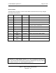
C-COM Satellite Systems Inc. Page 123 of 128 10.1. Appendix 1: Default Limits and Configuration Data Tables Compass Reading Elevation PLATFORM TYPES A1800A A1200C /B/C/D COMPASS READING ELEVATION 32 A0980B A0740B A0660A 35 25 25 32 Table 1: Compass Reading Elevation Default Values Elevation Offset A1800A/ B/C/D 45.00 EL OFFSET PLATFORM TYPES A1200C A1200P 31.00 42.00 A0980B A0740B A0660A 31.00 31.00 35.00 Table 2: Default Elevation Offsets.
C-COM Satellite Systems Inc. Page 124 of 128 Default Platform Speeds and Limits EL SLOW EL CURRENT6 EL CURRENT9 AZ SLOW AZ CURRENT6 AZ CURRENT9 PL SLOW PL CURRENT6 PL CURRENT9 PLATFORM TYPES A1800A/ A1200P B 6 6 7.00 4.5 12.00 6.5 6 5 7.00 4.0 12.00 10.0 6 4 1.0 1.5 2.0 2 Table 5 A1200C A0980B A0740B A0660A 6 7.00 12.00 6 7.00 12.00 6 1.0 2.0 4 7.00 12.00 4 7.00 12.00 7 1.0 2.0 4 7.00 12.00 4 7.00 12.00 7 1.0 2.0 4 7.00 12.00 4 7.00 12.00 7 1.0 2.
C-COM Satellite Systems Inc. Page 125 of 128 10.2.
C-COM Satellite Systems Inc.
C-COM Satellite Systems Inc.
C-COM Satellite Systems Inc. Page 128 of 128 10.3. Appendix 3: Router Configuration Example iNetVu™ Mobile Platform GPS Antenna TX SENSOR CABLE RX MOTOR CONTROL 7000 CTRL: DHCP OR Static: IP: 192.168.1.3 SUB: 255.255.255.0 GW: 192.168.1.1 ! 90 - 264VAC RX IN PC: DHCP Computer OR Static: IP: 192.168.1.2 SUB: 255.255.255.0 GW: 192.168.1.1 Router WAN Port TX OUT Motor Control Cable Satellite Modem / VSAT Modem Example: 70.232.247.