
User manual

C-COM Satellite Systems Inc. Page 78 of 128
iNetVu™ 7000 Controller User Manual
Revision 1.19
EL Motor Current
Current drawn for Elevation Motor (in Amperes)
AZ Motor Current
Current drawn for Azimuth Motor (in Amperes)
PL Motor Current
Current drawn for Polarization Motor (in Amperes)
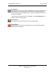
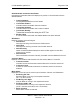
Message Panel
Displays real-time status updates, system messages, and error codes.
Fig. 59: Message Panel
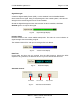
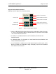
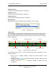
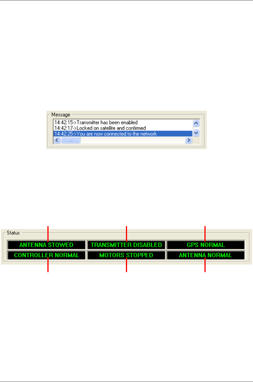
Status Panel
The Status Panel describes system operations that are either imminent, taking place, or
the current status of that component. The Status Panel is located at the bottom of the
Basic Controls and Advanced Controls menus, and has a set of four and six message
blocks, respectively.
Fig. 60: Advanced Controls - Status Panel
The indicators notify the user of any actions taking place with a combination of color-
coated messages.
Solid “GREEN” messages indicate a stable and normal condition for that
component.
Flashing or solid “LIGHT BLUE” messages indicate a change in status occurring
that the user should be aware of.
Flashing “RED” and “YELLOW” messages indicates a problem with that
component.
System Status Satellite Modem Status GPS Status
Controller Status Motor Status Antenna Sensor Status