
User manual

Duino Open
Item no. 1378656
Quick guide
Intended Use
The C-Control Duino Open is an electronic component of the integrated circuit type. The
C-Control serves as the programmable control of electrical and electronic devices. Design and
operation of these devices must comply with applicable European Approval Guidelines (CE).
The C-Control must not be galvanically connected to voltage via protective low voltage. Con-
nection to systems with higher voltage must be performed only via VDE approved components.
At that, the prescribed air gaps and leakage paths must be observed, as well as adequate
measures taken for protection against touching dangerous live parts.
Electronic components with high frequency clock signals and steep pulse slopes operate on
the board C-Control Duino Open. Misuse of the unit may lead to emission of electromagnetic
interference signals. Adequate measures (e.g., use of inductors, limiting resistors, blocking
capacitors and shielding) for compliance with legally prescribed maximum values is the re-
sponsibility of the end user.
The maximum permissible length of the connected cables without additional measures is 0.25
metres (except for serial ports). Operation of the C-Control may be affected by strong alternat-
ing electromagnetic elds or interference pulses. System reset and restart may be needed,
where appropriate.
Power is supplied either by an external power adapter (not included in the supply schedule)
or via USB.
Follow the safety instructions and all other information in this operation manual.
This product complies with the applicable national and European requirements. All names of
companies and products are the trademarks of the respective owners. All rights reserved.
Package Contents
• Duino Open
• Quick guide
Safety Instructions
The warranty will be void in the event of damage caused by failure to observe
these safety instructions! We do not assume any liability for any resulting
damage!
We shall not accept liability for damage to property or personal injury caused
by incorrect handling or non-compliance with the safety instructions! In such
cases, the warranty will be null and void.
• Unauthorised conversion and/or modication of the product is not allowed for
safety and approval reasons (CE).
• The product is not a toy and should be kept out of the reach of children.
• During assembly/disassembly the appropriate safety precautions against static
charge should be taken (e.g., earth connection, insulating support, etc.).
• When connecting external modules take note of the maximum permissible current
and voltage values for each pin.
Wrong polarity, application of excess voltage or current may lead to immediate
destruction of the product.
• The product must not get damp or wet.
• Handle the product with care; it can be damaged by impacts, blows or falls even
from a low height.
• Do not carelessly leave the packaging material lying around, since it could be-
come a dangerous plaything for children.
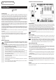
Connections and Control Elements
Programming
The C-Control Duino Open Board is equipped with a USB port for transferring and debugging
of user programmes. Communication between PC and the board occurs via the board USB
controller (of the Silibas CP2104 type) and UART pins of the ATmega328 microcontroller.
An Arduino™ UNO bootloader is pre-installed at the ATmega328 microcontroller, which ena-
bles transferring your programme from PC via USB to the microcontroller without any additional
programming device. It requires an appropriate USB cable (USB plug type A to USB plug type
B, not included in the supply schedule). Select the board "Arduino UNO" in the Arduino™
development environment.
The Arduino™ development environment can be downloaded at www.arduino.cc.
Power supply
The board can be supplied via either the "POWER" socket or USB. If no power supply unit
(output voltage 7 - 12 V/DC, 500 mA) is connected to the "POWER" socket the board will be
powered via the USB port automatically.
When experimenting, it is advisable to operate the board connected via a separate
external USB hub (with its own power adapter) rather than directly to the USB port
of the computer. In case of a failure (e.g., short circuit during the experiment) only
USB hub would be damaged but not the valuable USB port of your computer.
Light emitting diodes
There are four LEDs (light emitting diodes) on the board:
• LED "L": This LED is freely available for the user and can be used as an output LED. The
LED is connected with the port 13 by a high-impedance FET. This output is not blocked by
this LED wiring, but can be further charged by up to ±40 mA.
• LED "RX": This LED is connected with the USB chip "CP2104" and signalises receiving data
from the USB chip (i.e. the LED ashes when the ATmega328 microcontroller is sending data
to the PC).
• LED "TX": This LED is connected with the USB chip "CP2104" and signalises sending data
by the USB chip (i.e. the LED ashes when data are being sent to the ATmega328 microcon-
troller from the PC).
• LED "ON": This LED lights up when the board is energised (via USB or power supply unit).
Switch
There is a slide switch on the board near the USB socket. It serves for switching the microcon-
troller operating voltage between 5 V/DC and 3.3 V/DC. Put the switch into "3.3 V" position if
you use shields or external components that require 3.3 V supply, and into "5 V" position - for
5 V components.
Button
The button designated as "RES" serves for reset of the ATmega328 microcontroller. In this way,
the programme is restarted.