INSTRUCTION MANUAL PLEASE READ ALL THE INSTRUCTIONS COMPLETELY BEFORE USE AND SAVE THIS MANUAL FOR FUTURE REFERENCE.
Before Use Please read IMPORTANT SAFETY INSTRUCTIONS on page 25 before use. It is important to read and understand all instructions. WARNING: TO PREVENT FIRE OR ELECTRIC SHOCK HAZARD, DO NOT EXPOSE THIS PRODUCT TO RAIN OR MOISTURE. CAUTION RISK OF ELECTRIC SHOCK DO NOT OPEN THE LIGHTNING FLASH AND ARROWHEAD WITHIN THE TRIANGLE IS A WARNING SIGN ALERTING YOU OF “DANGEROUS VOLTAGE” INSIDE THE RADIO. CAUTION: TO REDUCE THE RISK OF ELECTRIC SHOCK, DO NOT REMOVE THE RADIO BACK.
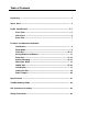
Table of Contents Unpacking ....................................................................................................... 2 Quick Start ..................................................................................................... 4 Radio Identification .................................................................................. 5-7 Front View ............................................................................................. 5 Side Views ...................................
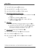
Quick Start 1. Turn “AM RF GAIN” control knob 2. Slide “AM SENSITIVITY” switch 3. Slide “FM/SW ANTENNA” switch 4. Select band by rotating band selection knobs: y full clockwise. H to “DISTANT” position. J to “INTERNAL” position. a) For AM band turn “AM/SW” knob to “WIDE”. i to “AM” and “AM/SW–FM” knob o b) For FM band turn “AM/SW” knob o to “MONO”. c) For SW turn “AM/SW” knob i to “SW1”, “SW2” or “SW3” and “AM/SW–FM” knob o to “WIDE.” 5.
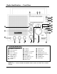
Radio Identification — Front View p [ ] Q W E R Y o I i T U O P { u y t r e w q } Front/Top Identification Q W E R T POWER or • SLEEP Timer Y MEMORY SET or • CLOCK SET U ALARM DUAL TIME Button LOCK Button Down or • MINUTE Up or • HOUR or 12/24 Hour Clock I • TIMER A O • TIMER B P MEMORY or • CHARGE { SW BAND Selection } RESET q TUNING Knob w DIAL SPEED Selection e VOLUME Control r BASS Control t y u i o p [ ] TREBLE Control AM RF GAIN Headphone Jack AM/SW BAND Selection AM/SW–FM Band S
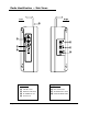
Radio Identification — Side Views Left Right F A G S H D J Left View A S D F Page 6 LINE OUT Jacks BATTERY SIZE Switch DC POWER IN Jack Right View G H J KEY LIGHT Switch AM SENSITIVITY Switch FM/SW ANTENNA Switch Radio Handle CCRadio SW
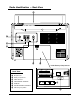
Radio Identification — Back View K d s a : L Inside Battery Compartment Back View SIZE AA 1.5V SIZE AA 1.5V SIZE D 1.5V K L : a s d f Whip Antenna SIZE AA 1.5V SIZE AA 1.5V Battery Compartment 9K 10K AM IF OUTPUT AM EXTERNAL ANTENNA SIZE D 1.5V SIZE D 1.5V SIZE D 1.
Features and Operation Explained — Front of Radio Introduction The CCRadio-SW can receive weaker signals, with superior audio, than perhaps any portable radio ever made. You are given much more control over how the radio works, sounds and picks up a signal. You can even deliver a digital signal to a computer for decoding. Learning how the radio works will help you with your audio experience. Please refer to the Radio Identification diagrams on pages 5-7 as you read through this instruction manual.
Features and Operation Explained — Front of Radio 2) It sets the “WORLD” or “LOCAL” time clock to the default time clock when the radio is “off”. To change the default display time clock, with the radio “off”, hold the button down for five seconds. The radio display will change displaying the word LOCAL or WORLD indicating the time clock that will now be the new default time clock. See “CLOCK SET” (page 10) to set the time on the default clock.
Features and Operation Explained — Front of Radio 1) It will increase the frequency one step at a time with each press and release of the button. 2) It will automatically search “up” in frequency until it finds a relatively strong station to stop on, when you press and hold the button for two seconds. 3) When used with “MEMSET” button Y it toggles memory number positions for storing stations to memory. See “MEMORY SET” (page 11) to set stations to memory.
Features and Operation Explained — Front of Radio clock to “UTC” (Universal Time Coordinated) the Time DIFF number is the number of hours between “LOCAL” time and “WORLD” time. As an example, San Francisco, CA, is 8 hours behind UTC. Set the “WORLD” time clock 8 hours ahead of “LOCAL” time, rotating the “TUNING” dial until the Time DIFF number is “+8”. 2) When the radio is “on”, the button stores stations to a Memory Preset number.
Features and Operation Explained — Front of Radio to before turning the radio “off”. The radio will play for 60 minutes. While the radio is playing, the will flash and the will also be displayed. To stop a “Timer” for the day but retain the alarm setting, press the “POWER” button. The “Timer” will then come on automatically the next day. Snooze: To snooze, press and release the “SNOOZE” bar [ on top of the radio, while the alarm is sounding. The alarm icon will flash on the display.
Features and Operation Explained — Front of Radio S on the left side of the radio. Install “AA” or “D” size rechargeable batteries such as Nickel Metal Hydride into the “AA” or “D” slots according to the diagram etched in the battery compartment. Be very careful to orientate the batteries correctly as labeled. Connect the radio to power using the supplied AC Adapter. While the radio is “off” and the radio is connected to a power source, press the “CHARGE” button.
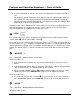
Features and Operation Explained — Front of Radio } RESET “RESET” is used to clear up the radio if it should become scrambled and the buttons do not respond, or if you wish to change “AM Tuning Steps”. To push the “RESET”, use the end of a paperclip and push it into the hole briefly. Stations stored in Memory are saved after you “reset” the radio. If you change the “AM Tuning Step” switch from 10 kHz to 9 kHz tune spacing, you must press the “RESET” to activate the change after you flip the switch.
Features and Operation Explained — Front of Radio Press and release the button and the word Fast will be displayed. When the radio is in AM band, the “TUNING” dial q will now tune in 10 kHz or 9 kHz steps, depending on the “AM Step Switch” f setting in the battery compartment (page 21). In SW band, tuning is 5 kHz steps, and in FM band tuning is 100 kHz steps. This setting may take some time to get use to. It allows fast access across the dial in all frequency ranges.
Features and Operation Explained — Front of Radio distortion, try reducing the “AM RF GAIN” for a clearer signal; and 2) Reduce static. When a signal is amplified by the RF amplifier, background noise is generally amplified out of proportion to the audio signal. This is due to the inherent nature of solid state chips. By reducing the “AM RF GAIN” control you can reduce static while keeping a decent audio signal. TUNING TIP: The “AM RF GAIN” knob should be set to full clockwise to begin.
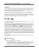
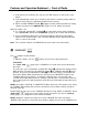
Features and Operation Explained — Front of Radio p LCD DISPLAY 1 2 3 4 5 6 12 7 11 10 9 [ 1) BATTERY Symbol 7) MEMORY Location (1 - 10) 2) AC ADAPTER Symbol 8) DIAL SPEED Indicators 3) SLEEP Timer/SNOOZE Status 9) FREQUENCY / CLOCK Display 4) KEY LOCK On/Off 10) DUAL TIME Indicator 5) ALARM Status and Type 11) Indicates BAND In Use 6) Signal Strength Meter 12) STEREO Reception 8 SNOOZE BAR The “SNOOZE” bar is used to pause an alarm. See “SETTING THE ALARM” on page 11.
Features and Operation Explained — Left Side A LINE OUT “LINE OUT” is used to send the radio’s audio to an external amplified speaker or stereo system. It is a fixed output level designed to work with external systems. The radio’s “VOLUME”, “BASS” and “TREBLE” controls do not function when using “LINE OUT” to an external system. An optional patch cord to your amplified speakers or stereo system will be needed for this connection.
Features and Operation Explained — Left, Right & Back F RADIO HANDLE The handle is made of a special, high-tensile strength plastic to resist breakage. It is designed to fold down when not in use. G KEY LIGHT SWITCH Setting the “KEY LIGHT” switch to “on” turns the button back light function “on”. When this switch is “on”, the front panel buttons will light for 8 seconds when any button is pressed.
Features and Operation Explained — Back of Radio Antenna”, set “FM/SW ANTENNA” switch J to “INTERNAL”, extend the “Whip Antenna” fully and try rotating it into different positions. It is best to try the radio with the “Whip Antenna” first. While on FM, try collapsing the last two telescopic elements for better reception. This length resonates better with FM band frequencies. Then try using external antennas if stations are weak or hard to receive.
Features and Operation Explained — Back of Radio ple antenna. A small diameter insulated stranded wire, about 60 feet in length is a good place to start. Antenna wire can be attached by pressing the spring loaded lever and inserting the wire. See “GROUND” jack s to complete the antenna. If you are not familiar with external wires we recommend hiring a qualified installer. See Safety Instructions on page 25. NOTE: AM as we commonly call it in the United States is MW or Medium Wave in the rest of the world.
Troubleshooting Guide The CCRadio SW will not turn on: 1. Make sure the “LOCK” is off. 2. Check the “BATTERY SELECTION” switch to make sure it is in the proper position. 3. Be sure that the batteries are installed correctly. 4. Make sure all batteries are good. 5. If using the AC Adapter, make sure that it is plugged fully into the power jack. The CCRadio SW has poor reception on FM and SW: 1. Check the “FM/SW ANTENNA” switch on the right side of the radio for the proper setting. 2.
Safety Instructions READ BEFORE OPERATING EQUIPMENT SAVE THESE INSTRUCTIONS To prevent damage to your radio or possible injury to you or others, read these safety precautions and instructions entirely before applying power to your radio. Keep these precautions and instructions where all who use this radio will read them. 1) COMMON CARE Check the radio, AC adapter, batteries and any accessories regularly. Do not use the radio if there is any sign of damage.
Model: CCRadio SW ANSI C63.4: 2003 THIS DEVICE COMPLIES WITH PART 15 OF THE FCC RULES. OPERATION IS SUBJECT TO THE FOLLOWING TWO CONDITIONS. 1) THIS DEVICE MAY NOT CAUSE HARMFUL INTERFERENCE, AND 2) THIS DEVICE MUST ACCEPT ANY INTERFERENCE RECEIVED, INCLUDING INTERFERENCE THAT MAY CAUSE UNDESIRED OPERATION. Notice: Any changes or modifications not expressly approved by the party responsible for compliance could void the user’s authority to operate the equipment.