
User Manual


Edition 09/2000
15
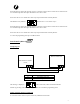
Wiring diagram with a magnetic stripe reader
7 8 9 10 111213
6 5 4 3 2 1
1 2 3 4 5 6 7 8 9 10 11 12 13 14 15 16 17 18 19 20 21 22 23 24
Proximty
ReaderRL1 RL2 RL3
AV ARPROG
V
25 26
ST1
L1
L2
L3
L4
L5
Input voltage
12V ~ or =
230 V
White
Green
Orange
Yellow
w
Grey
Brown
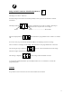
Wiring between D534 – UCA3
Module UCA3
Reader1 Reader2
1 NC NC
2 15 5
3 18 8
4 16 6
5 3 3
6 4 4
Interface
Module
D534