
Installation User Manual
INSTALLATION
1. A8-128 Power Management System should be
installed as close to the main battery compartment
as possible to minimize the effect of voltage drops
along power cables. The PMS is grounded to its case
and will require external grounding by installing
directly on grounded chassis (connected to battery
ground) or direct grounding through properly sized
cable installed on one of the six screws holding the
PMS to chassis and then connected directly to the
battery ground. See below for stacking order and
torque.
Make sure cables are properly sized and
supported within 305mm/12 in. of PMS.
Failure to do so can cause component
damage.
2. Cable connections (see below for stacking order and
torque):
a. Connect "MAIN" cable from "MAIN" terminal on
PMS to either the alternator output cable or posi-
tive terminal of the "Main" (engine starter) battery.
See below for stacking order and torque on PMS
"MAIN" terminal. Make sure the LED located next to
the terminal remains visible after cable is connected.
Make sure cables are properly sized and
supported within 305mm/12 in. of PMS.
Failure to do so can cause component
damage.
Page 1 of 1
II201A
A8-128
Power Management System
Installation Instructions
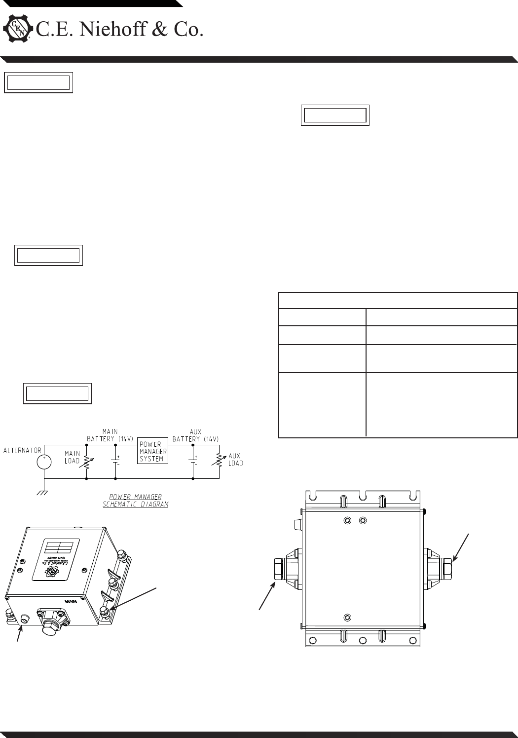
Figure 1 – A8-128 Power Management System (PMS)
If you have questions about your alternator or any of these instructions, or if you need to locate a Factory Authorized Service Dealer, please contact us at:
C. E. Niehoff & Co.• 2021 Lee Street • Evanston, IL 60202 USA
TEL: 800.643.4633 USA and Canada • TEL: 847.866.6030 outside USA and Canada • FAX: 847.492.1242
E-mail us at service@CENiehoff.com
Mounting hardware
(6 places)
torque to
8.5 Nm/75 lb. in.:
M5x16mm screw,
Belleville washer
Ground terminal (when used)
LED
This symbol is used to indicate the presence
of hazards that can cause minor personal
injury or equipment damage.
CAUTION
b. Connect "AUX" cable from "AUX" terminal on PMS to
either an auxiliary load or the positive terminal of
an Auxiliary Battery system.
Make sure cables are properly sized
and supported within 305mm/12 in.
of PMS. Failure to do so can cause
component damage.
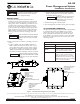
3. Schematic diagram is shown below.
4. Test all components to make sure they operate properly.
A8-128 SYSTEM OPERATION
A8-128 Power Management System (PMS) is programmed
to automatically connect the "MAIN" source positive
polarity (B+) to the positive polarity "AUX" battery or
loads. The PMS automatically disconnects the "AUX"
from "MAIN" if an overload condition occurs. The PMS
functions as both battery isolator and automatic load
switching system.
CAUTION
CAUTION
CAUTION
LED COLOR
STATUS
A8-128 LED Status
No power present on "MAIN" terminal.
OFF
Power of "MAIN" terminal appears at
"AUX" terminal (switch is closed).
GREEN
Power of "MAIN" terminal does not
appear at "AUX" terminal (switch is
open). Normally due to an overload
condition that caused switch to open.
PMS automatically resets by resolving
cause of overload condition.
AMBER
"MAIN" terminal torque
to 15 Nm/11 lb. ft.:
M10x1.5 bolt,
Lock washer
Washer
"MAIN" cable terminal
"AUX" terminal torque
to 15 Nm/11 lb. ft.:
M10x1.5 bolt,
Lock washer
Washer
"AUX" cable terminal