6121 Baker Road, Suite 108 Minnetonka, MN 55345 Phone (952) 933-6190 Fax (952) 933-6223 1-800-274-4284 www.chtechnology.com Thank you for downloading this document from C&H Technology, Inc. Please contact the C&H Technology team for the following questions - Technical Application Assembly Availability Pricing Phone – 1-800-274-4284 E-Mail – sales@chtechnology.com www.chtechnology.com - SPECIALISTS IN POWER ELECTRONIC COMPONENTS AND ASSEMBLIES - www.chtechnology.
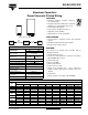
051/053 PEC-PW Vishay BCcomponents Aluminum Capacitors Power Economic Printed Wiring FEATURES • Polarized aluminum non-solid electrolyte electrolytic capacitors, • Large types with reduced dimensions, cylindrical aluminum case, insulated with a blue sleeve RoHS COMPLIANT • Provided with keyed polarity • Long useful life: 12 000 hours at 85 °C • High ripple current capability • High resistance to shock and vibration APPLICATIONS Fig.
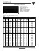
051/053 PEC-PW Aluminum Capacitors Power Economic Printed Wiring Vishay BCcomponents SELECTION CHART FOR CR, UR AND RELEVANT NOMINAL CASE SIZES (Ø D x L in mm) CR (µF) UR (V) 3300 4700 6800 10 000 15 000 22 000 33 000 47 000 68 000 100 000 150 000 10 16 25 40 63 100 25 x 30 25 x 40 30 x 40 35 x 40 35 x 50 40 x 40 40 x 50 40 x 70 40 x 100 25 x 30 25 x 40 30 x 40 35 x 40 35 x 50 40 x 40 40 x 50 40 x 70 40 x 100 - 25 x 30 25 x 40 30 x 40 35 x 40 35 x 50 40 x 40 40 x 50 40 x 70 40 x 100 - 25 x 30
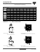
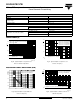
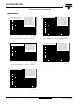
051/053 PEC-PW Aluminum Capacitors Power Economic Printed Wiring Vishay BCcomponents 2.5 3 - 2 Ø D + 1 max. 3 - 15 ± 0.1 L 1 L + 5 max. 1.3 (4x) 7.5 ± 0.1 17.5 ± 0.1 MGB267-1 4.9 ± 0.2 Case ∅ D = 35 mm Fig. 7 Mounting hole diagram viewed from component side Case ∅ D = 35 mm Fig.6 Printed wiring pin version 2.5 3 - Ø D + 1 max. 2 4 20 ± 0.1 1 L L + 5 max. 1.3 (5 x) 10 ± 0.1 17.5 ± 0.1 5.1 ± 0.1 20 ± 0.1 Case ∅ D = 40 mm Case ∅ D = 40 mm Fig.
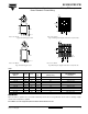
051/053 PEC-PW Aluminum Capacitors Power Economic Printed Wiring Vishay BCcomponents ORDERING EXAMPLE . ELECTRICAL DATA SYMBOL DESCRIPTION Electrolytic capacitor 051 series CR rated capacitance at 100 Hz IR rated RMS ripple current at 100 Hz, 85 °C or at 20 kHz, 70 °C IL1 max. leakage current after 1 minute at UR IL5 max. leakage current after 5 minutes at UR ESR max. equivalent series resistance at 100 Hz Z max.
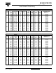
051/053 PEC-PW Aluminum Capacitors Power Economic Printed Wiring Vishay BCcomponents ELECTRICAL DATA AND ORDERING INFORMATION 051 SERIES UR (V) 63 100 CR 100 Hz (µF) NOMINAL CASE SIZE ØDxL (mm) IR 100 Hz 85 °C (A) 2200 3300 4700 6800 10 000 10 000 15 000 22 000 680 1000 1500 2200 3300 3300 4700 6800 10 000 25 x 30 25 x 40 30 x 40 35 x 40 35 x 50 40 x 40 40 x 70 40 x 100 25 x 30 25 x 40 30 x 40 35 x 40 35 x 50 40 x 40 40 x 50 40 x 70 40 x 100 2.5 3.3 4.1 4.5 5.4 4.6 7.5 10.0 1.74 2.34 2.95 3.69 4.
051/053 PEC-PW Aluminum Capacitors Power Economic Printed Wiring Vishay BCcomponents ADDITIONAL ELECTRICAL DATA PARAMETER CONDITIONS VALUE Voltage Surge voltage ≤ 250 V versions Us = 1.15 x UR ≥ 385 V versions Us = 1.1 x UR Urev ≤ 1 V Reverse voltage Current Leakage current After 1 minute at UR IL1 ≤ 0.006 CR x UR + 4 µA After 5 minutes at UR IL5 ≤ 0.002 CR x UR + 4 µA Case Ø D = 25 mm max. 25 nH Inductance Equivalent series inductance (ESL) Case Ø D = 30 and 35 mm max.
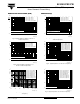
051/053 PEC-PW Aluminum Capacitors Power Economic Printed Wiring EQUIVALENT RESISTANCE (ESR) Vishay BCcomponents IMPEDANCE (Z) 102 102 ESR ESR0 Curve 1: UR = 385 V Curve 2: UR = 200 V Curve 3: UR = 100 V Curve 4: UR = 10 V to 63 V 1 Z Z0 10 Curve 1: UR = 385 V Curve 2: UR = 200 V Curve 3: UR = 100 V Curve 4: UR = 10 V to 63 V 1 2 3 4 10 2 3 4 4 2, 3 1 1 1 4 2, 3 1 ESR0 = typical at 20 °C, 100 Hz Z0 = impedance at 20 °C, 10 kHz Case Ø D x L = 35 x 50, 40 x 40, 40 x 50, 40 x 70 and 40 x 100
051/053 PEC-PW Aluminum Capacitors Power Economic Printed Wiring Vishay BCcomponents IMPEDANCE (Z) 2 10 10 Case Ø D x L = 35 x 50 mm and 35 x 40 mm 1 Z (Ω) 10 Curve 1: 220 µF, 385 V Curve 2: 4700 µF, 200 V Curve 3: 2200 µF, 100 V Curve 4: 6800µF, 63 V Curve 5: 10 000 µF, 40 V Curve 6: 15 000 µF, 25 V Curve 7: 22 000 µF, 16 V Curve 8: 33 000 µF, 10 V 2 3 1 10 Curve 1: 330 µF, 385 V Curve 2: 680 µF, 200 V Curve 3: 3300 µF, 100 V Curve 4: 10 000µF, 63 V Curve 5: 15 000 µF, 40 V Curve 6: 22 000 µF, 25
051/053 PEC-PW Aluminum Capacitors Power Economic Printed Wiring Vishay BCcomponents RIPPLE CURRENT AND USEFUL LIFE MGA453 2.4 IA 2.3 IR 2.2 2.1 2.0 1.9 1.8 1.7 1 1.6 2 1. 5 1. 2 1.5 5 2. 3 1.4 4 8 10 15 20 30 Fig.25 Multiplier of useful life as a function of ambient temperature and ripple current load. (1) 45 0 6 1.2 1.1 1.0 0.8 0.5 0.0 5 1.
Legal Disclaimer Notice Vishay Disclaimer All product specifications and data are subject to change without notice. Vishay Intertechnology, Inc., its affiliates, agents, and employees, and all persons acting on its or their behalf (collectively, “Vishay”), disclaim any and all liability for any errors, inaccuracies or incompleteness contained herein or in any other disclosure relating to any product.