6121 Baker Road, Suite 108 Minnetonka, MN 55345 Phone (952) 933-6190 Fax (952) 933-6223 1-800-274-4284 www.chtechnology.com Thank you for downloading this document from C&H Technology, Inc. Please contact the C&H Technology team for the following questions - Technical Application Assembly Availability Pricing Phone – 1-800-274-4284 E-Mail – sales@chtechnology.com www.chtechnology.com - SPECIALISTS IN POWER ELECTRONIC COMPONENTS AND ASSEMBLIES - www.chtechnology.
Bulletin I2405 rev.
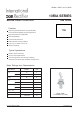
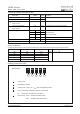
10RIA Series Bulletin I2405 rev. B 04/06 ELECTRICAL SPECIFICATIONS Voltage Ratings Type number Voltage Code V DRM/V RRM, max. repetitive peak and off-state voltage (1) V 10 20 10RIA VRSM , maximum nonrepetitive peak voltage (2) V I DRM/I RRM max. 100 150 20 200 300 40 400 500 60 600 700 80 800 900 100 1000 1100 120 1200 1300 @ TJ = TJ max.
10RIA Series Bulletin I2405 rev. B 04/06 Switching Parameter di/dt 10RIA Units Max. rate of rise of turned-on current TJ = TJ max., VDM = rated VDRM VDRM ≤ 600V 200 VDRM ≤ 800V 180 VDRM ≤ 1000V 160 VDRM ≤ 1600V 150 tgt Typical turn-on time trr Typical reverse recovery time Conditions A/μs Gate pulse = 20V, 15Ω, tp = 6μs, tr = 0.1μs max. ITM = (2x rated di/dt) A 0.9 TJ = 25°C, at = rated VDRM/VRRM, TJ = 125°C 4 μs TJ = TJ max.
10RIA Series Bulletin I2405 rev. B 04/06 Thermal and Mechanical Specification Parameter 10RIA Units Conditions TJ Max. operating temperature range - 65 to 125 °C Tstg Max. storage temperature range - 65 to 125 °C 1.85 K/W DC operation 0.35 K/W Mounting surface, smooth, flat and greased RthJC Max. thermal resistance, junction to case RthCS Max. thermal resistance, case to heatsink T Mounting torque wt to nut to device 20(27.5) 25 lbf-in Lubricated threads 0.23(0.32) 0.29 kgf.
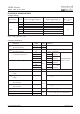
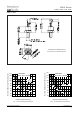
10RIA Series Bulletin I2405 rev. B 04/06 Outline Table Case Style TO-208AA (TO-48) 130 10RIA Series RthJC (DC) = 1.85 K/W 120 110 100 90 Conduction Angle 80 30° 60° 70 90° 60 120° 180° 50 40 0 2 4 6 8 10 12 14 16 18 Maximum Allowable Case Temperature (°C) Maximum Allowable Case Temperature (°C) All dimensions in millimeters (inches) 130 10RIA Series RthJC (DC) = 1.
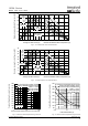
10RIA Series 35 30 5K /W 7K /W Conduction Angle 10 10RIA Series TJ = 125°C 5 2 4 6 8 10 12 14 16 Average On-state Current (A) R 4K /W RMS Limit 0 ta el -D 3K /W 15 0 W K/ 20 K/ W 1 25 2 = 180° 120° 90° 60° 30° SA R th Maximum Average On-state Power Loss (W) Bulletin I2405 rev. B 04/06 10 K /W 0 18 25 50 75 100 125 Maximum Allowable Ambient Temperature (°C) 45 DC 180° 120° 90° 60° 30° 40 35 30 R SA th Maximum Average On-state Power Loss (W) Fig.
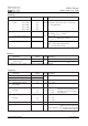
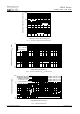
10RIA Series Instantaneous On-state Current (A) Bulletin I2405 rev. B 04/06 1000 100 TJ = 25°C TJ = 125°C 10 10RIA Series 1 0.5 1 1.5 2 2.5 3 3.5 4 Instantaneous On-state Voltage (V) Transient Thermal Impedance ZthJC (K/W) Fig. 7 - Forward Voltage Drop Characteristics 10 Steady State Value R thJC = 1.85 K/W (DC Operation) 1 10RIA Series 0.1 0.001 0.01 0.1 1 10 Square Wave Pulse Duration (s) Fig.
10RIA Series Bulletin I2405 rev. B 04/06 Data and specifications subject to change without notice. This product has been designed and qualified for Industrial and Consumer Level and Lead-Free. Qualification Standards can be found on IR's Web site. IR WORLD HEADQUARTERS: 233 Kansas St., El Segundo, California 90245, USA Tel: (310) 252-7105 TAC Fax: (310) 252-7309 03/06 Document Number: 93689 www.vishay.