6121 Baker Road, Suite 108 Minnetonka, MN 55345 Phone (952) 933-6190 Fax (952) 933-6223 1-800-274-4284 www.chtechnology.com Thank you for downloading this document from C&H Technology, Inc. Please contact the C&H Technology team for the following questions Technical ● Application ● Assembly ● Availability ● Pricing Phone – 1-800-274-4284 E-Mail – sales@chtechnology.com www.chtechnology.com - SPECIALISTS IN POWER ELECTRONIC COMPONENTS AND ASSEMBLIES - www.chtechnology.
110RKI...PbF, 111RKI...
110RKI...PbF, 111RKI...PbF Series Vishay High Power Products Phase Control Thyristors (Stud Version), 110 A ABSOLUTE MAXIMUM RATINGS PARAMETER SYMBOL Maximum average on-state current at case temperature IT(AV) Maximum RMS on-state current IT(RMS) TEST CONDITIONS 180° conduction, half sine wave DC at 83 °C case temperature t = 10 ms Maximum peak, one-cycle non-repetitive surge current ITSM t = 8.3 ms t = 10 ms t = 8.3 ms t = 10 ms Maximum I2t for fusing I2t t = 8.
110RKI...PbF, 111RKI...PbF Series Phase Control Thyristors (Stud Version), 110 A Vishay High Power Products TRIGGERING PARAMETER SYMBOL Maximum peak gate power PGM Maximum average gate power PG(AV) Maximum peak positive gate current IGM Maximum peak positive gate voltage + VGM Maximum peak negative gate voltage - VGM TEST CONDITIONS IGT 12 TJ = TJ maximum, f = 50 Hz, d% = 50 3.
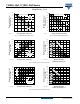
110RKI...PbF, 111RKI...PbF Series Vishay High Power Products Phase Control Thyristors (Stud Version), 110 A 140 140 RthJC (DC) = 0.27 K/W Maximum Allowable Case Temperature (°C) Maximum Allowable Case Temperature (°C) RthJC (DC) = 0.
110RKI...PbF, 111RKI...PbF Series Phase Control Thyristors (Stud Version), 110 A 2500 2000 1600 Peak Half Sine Wave On-State Current (A) At any rated load condition and with rated VRRM applied following surge. Initial TJ = 140 °C at 60 Hz 0.0083 s at 50 Hz 0.0100 s 1800 Peak Half Sine Wave On-State Current (A) Vishay High Power Products 1400 1200 Maximum non-repetitive surge current versus pulse train duration. Control of conduction may not be maintained.
110RKI...PbF, 111RKI...PbF Series Vishay High Power Products Phase Control Thyristors (Stud Version), 110 A 10 Rectangular gate pulse (a) Recommended load line for rated dI/dt: 20 V, 30 Ω, tr ≤ 0.5 μs, tp ≥ 6 μs (b) Recommended load line for ≤ 30 % rated dI/dt: 15 V, 40 Ω, tr ≤ 1 μs, tp ≥ 6 μs TJ = 40 °C VGD 0.1 0.
Outline Dimensions Vishay High Power Products TO-209AC (TO-94) for 110RKI and 111RKI Series DIMENSIONS in millimeters (inches) Ceramic housing 37 )M IN . 2.6 (0.10) MAX. 16.5 (0.65) MAX. (0. Ø 8.5 (0.33) 9 .5 Ø 4.3 (0.17) Flexible lead 20 (0.79) MIN. C.S. 16 mm2 (0.025 s.i.) C.S. 0.4 mm2 Red silicon rubber (0.0006 s.i.) Red cathode 157 (6.18) 170 (6.69) White gate 215 ± 10 (8.46 ± 0.39) Fast-on terminals Red shrink 55 (2.16) MIN. White shrink AMP. 280000-1 REF-250 Ø 22.5 (0.88) MAX.
Legal Disclaimer Notice Vishay Disclaimer All product specifications and data are subject to change without notice. Vishay Intertechnology, Inc., its affiliates, agents, and employees, and all persons acting on its or their behalf (collectively, “Vishay”), disclaim any and all liability for any errors, inaccuracies or incompleteness contained herein or in any other disclosure relating to any product.