
Manual


www.vishay.com For technical questions, contact: diodes-tech@vishay.com
Document Number: 93203
4 Revision: 16-Aug-08
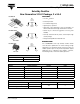
113CNQ100A
Vishay High Power Products
Schottky Rectifier
New Generation 3
D-61 Package, 2 x 55 A
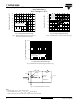
Fig. 5 - Maximum Allowable Case Temperature vs.
Average Forward Current (Per Leg)
Fig. 6 - Forward Power Loss Characteristics (Per Leg)
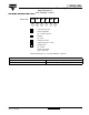
Fig. 7 - Maximum Non-Repetitive Surge Current (Per Leg)
Fig. 8 - Unclamped Inductive Test Circuit
Note
(1)
Formula used: T
C
= T
J
- (Pd + Pd
REV
) x R
thJC
;
Pd = Forward power loss = I
F(AV)
x V
FM
at (I
F(AV)
/D) (see fig. 6);
Pd
REV
= Inverse power loss = V
R1
x I
R
(1 - D); I
R
at V
R1
= 80 % rated V
R
I
F(AV)
- Average Forward Current (A)
Allowable Case Temperature (°C)
110
120
140
150
170
180
030609010 20 40 50 70 80
DC
See note (1)
Square wave (D = 0.50)
80 % rated V
R
applied
130
160
I
F(AV)
- Average Forward Current (A)
Average Power Loss (W)
010
20
30 40
50 60 80
0
10
20
40
70
30
50
60
DC
RMS limit
D = 0.75
D = 0.50
D = 0.33
D = 0.25
D = 0.20
t
p
- Square Wave Pulse Duration (µs)
I
FSM
- Non-Repetitive Surge Current (A)
10
100
1000
10 000
100
10 000
1000
At any rated load condition and
with rated V
RRM
applied
following surge
Current
monitor
High-speed
switch
D.U.T.
R
g
= 25 Ω
+
Freewheel
diode
V
d
= 25 V
L
IRFP460
40HFL40S02