6121 Baker Road, Suite 108 Minnetonka, MN 55345 Phone (952) 933-6190 Fax (952) 933-6223 1-800-274-4284 www.chtechnology.com Thank you for downloading this document from C&H Technology, Inc. Please contact the C&H Technology team for the following questions - Technical Application Assembly Availability Pricing Phone – 1-800-274-4284 E-Mail – sales@chtechnology.com www.chtechnology.com - SPECIALISTS IN POWER ELECTRONIC COMPONENTS AND ASSEMBLIES - www.chtechnology.
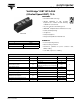
GA75TS120UPbF Vishay High Power Products "Half-Bridge" IGBT INT-A-PAK (Ultrafast Speed IGBT), 75 A FEATURES • Generation 4 IGBT technology • Ultrafast: Optimized for high operating frequencies 8 to 40 kHz in hard switching, > 200 kHz in resonant mode RoHS COMPLIANT • Very low conduction and switching losses • HEXFRED® antiparallel diodes with ultrasoft recovery • Industry standard package • UL approved INT-A-PAK • Totally lead (Pb)-free • Designed and qualified for industrial level BENEFITS PRODUCT SU
GA75TS120UPbF Vishay High Power Products "Half-Bridge" IGBT INT-A-PAK (Ultrafast Speed IGBT), 75 A ELECTRICAL CHARACTERISTICS (TJ = 25 °C unless otherwise specified) PARAMETER SYMBOL Collector to emitter breakdown voltage V(BR)CES Collector to emitter voltage VCE(on) Gate threshold voltage VGE(th) Temperature coefficient of threshold voltage Forward transconductance ΔVGE(th)/ΔTJ gfe Collector to emitter leaking current ICES Diode forward voltage VF Gate to emitter leakage current IGES TEST C
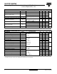
GA75TS120UPbF "Half-Bridge" IGBT INT-A-PAK Vishay High Power Products (Ultrafast Speed IGBT), 75 A THERMAL AND MECHANICAL CHARACTERISTICS PARAMETER SYMBOL MAX. - 0.32 - 0.35 0.1 - case to heatsink - 4.0 case to terminal 1, 2 and 3 (for screws M5 x 0.8) - 3.0 200 - IGBT Thermal resistance, junction to case RθJC Diode Thermal resistance, case to sink per module Mounting torque TYP.
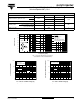
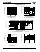
GA75TS120UPbF Vishay High Power Products "Half-Bridge" IGBT INT-A-PAK VCE - Collector to Emitter Voltage (V) (Ultrafast Speed IGBT), 75 A TC - Case Temperature (°C) 160 140 120 DC 100 80 60 40 20 0 0 20 40 60 80 100 120 3.0 IC = 150 A 2.5 IC = 75 A 2.0 IC = 37 A VGE = 15 V 500 µs pulse width 1.5 0 30 60 90 120 150 TJ - Junction Temperature (°C) Maximum DC Collector Current (A) Fig. 4 - Case Temperature vs. Maximum Collector Current Fig. 5 - Typical Collector to Emitter Voltage vs.
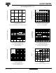
GA75TS120UPbF "Half-Bridge" IGBT INT-A-PAK Vishay High Power Products (Ultrafast Speed IGBT), 75 A 200 VGE = 20 V TJ = 125 °C VCE measured at terminal (peak voltage) IC - Collector Current (A) Total Switching Losses (mJ) 26 24 22 20 150 100 50 Safe operating area 0 18 10 20 30 40 50 0 800 1000 1200 RG - Gate Resistance (Ω) VCE - Collector to Emitter Voltage (V) Fig. 12 - Reverse Bias SOA 1400 1000 IF - Instantaneous Forward Current (A) Total Switching Losses (mJ) 600 Fig.
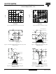
GA75TS120UPbF Vishay High Power Products "Half-Bridge" IGBT INT-A-PAK (Ultrafast Speed IGBT), 75 A 200 250 VR = 720 V TJ = 125 °C TJ = 25 °C IRRM (A) trr (ns) 200 IF = 150 A IF = 75 A IF = 37 A 160 IF = 150 A IF = 75 A IF = 37 A 120 80 150 VR = 720 V TJ = 125 °C TJ = 25 °C 40 100 500 1000 2000 1500 0 500 1000 dIF/dt (A/µs) dIF/dt (A/µs) Fig. 15 - Typical Reverse Recovery Time vs. dIF/dt Fig. 16 - Typical Recovery Current vs. dIF/dt L2 L1 Gate voltage D.U.T.
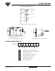
GA75TS120UPbF "Half-Bridge" IGBT INT-A-PAK Vishay High Power Products (Ultrafast Speed IGBT), 75 A VG Gate signal device under test Current D.U.T. Voltage in D.U.T. Current in D1 t0 t1 t2 Fig. 17e - Macro Waveforms for Figure 18a‘s Test Circuit L 1000 V D.U.T. VC* 50 V RL = 0 - 600 V 6000 µF 100 V 600 V 4 x IC at 25 °C * Driver same type as D.U.T.; VC = 80 % of VCE (max) Note: Due to the 50 V power supply, pulse width and inductor will increase to obtain rated Id Fig.
GA75TS120UPbF Vishay High Power Products "Half-Bridge" IGBT INT-A-PAK (Ultrafast Speed IGBT), 75 A CIRCUIT CONFIGURATION 3 6 7 1 4 5 2 LINKS TO RELATED DOCUMENTS Dimensions www.vishay.com 8 http://www.vishay.com/doc?95173 For technical questions, contact: ind-modules@vishay.