
Instruction Manual

Document Number: 94427 For technical questions, contact: ind-modules@vishay.com
www.vishay.com
Revision: 18-Jan-08 3
GA75TS120UPbF
"Half-Bridge" IGBT INT-A-PAK
(Ultrafast Speed IGBT), 75 A
Vishay High Power Products
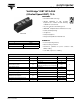
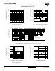
Fig. 1 - Typical Load Current vs. Frequency
(Load Current = I
RMS
of Fundamental)
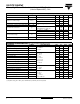
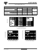
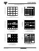
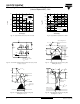
Fig. 2 - Typical Output Characteristics Fig. 3 - Typical Transfer Characteristics
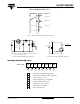
THERMAL AND MECHANICAL CHARACTERISTICS
PARAMETER SYMBOL TYP. MAX. UNITS
Thermal resistance, junction to case
IGBT
R
θJC
-0.32
°C/WDiode - 0.35
Thermal resistance, case to sink per module R
θCS
0.1 -
Mounting torque
case to heatsink - 4.0
Nm
case to terminal 1, 2 and 3
(for screws M5 x 0.8)
-3.0
Weight of module 200 - g
0.1 1 10 100
0
20
40
60
80
f - Frequency (kHz)
Load Current (A)
For both:
Duty cycle: 50 %
T
J
= 125 °C
T
sink
= 90 °C
Gate drive as specified
Power dissipation = 83 W
Ideal diodes
60 % of rated
voltage
Square wave:
70
50
30
10
I
0.5 1.0 1.5 2.0 2.5 3.0
1
10
100
1000
V
GE
= 15 V
500 µs pulse width
25 °C
125 °C
V
CE
- Collector to Emitter Voltage (V)
I
C
- Collector Current (A)
3.5
4.0 4.5 5.0 5.5 6.0 6.5 7.0 7.5
1
10
100
1000
V
GE
- Gate to Emitter Voltage (V)
I
C
- Collector to Emitter Current (A)
V
GE
= 20 V
500 µs pulse width
125 °C
25 °C
8.0