6121 Baker Road, Suite 108 Minnetonka, MN 55345 Phone (952) 933-6190 Fax (952) 933-6223 1-800-274-4284 www.chtechnology.com Thank you for downloading this document from C&H Technology, Inc. Please contact the C&H Technology team for the following questions - Technical Application Assembly Availability Pricing Phone – 1-800-274-4284 E-Mail – sales@chtechnology.com www.chtechnology.com - SPECIALISTS IN POWER ELECTRONIC COMPONENTS AND ASSEMBLIES - www.chtechnology.
GB75YF120N Vishay High Power Products IGBT Fourpack Module, 75 A FEATURES • Square RBSOA • HEXFRED® low Qrr, low switching energy RoHS COMPLIANT • Positive VCE(on) temperature coefficient • Copper baseplate • Low stray inductance design • Operating frequencies 8 to 60 kHz ECONO2 4PACK • Designed and qualified for industrial market BENEFITS • Benchmark efficiency for SMPS appreciation in particular HF welding PRODUCT SUMMARY VCES 1200 V IC at TC = 67 °C 75 A VCE(on) (typical) 3.
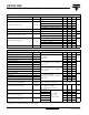
GB75YF120N Vishay High Power Products IGBT Fourpack Module, 75 A ELECTRICAL SPECIFICATIONS (TJ = 25 °C unless otherwise specified) PARAMETER SYMBOL Collector to emitter breakdown voltage VBR(CES) Collector to emitter voltage VCE(ON) Gate threshold voltage VGE(th) Threshold voltage temperature coefficient Zero gate voltage collector current Diode forward voltage drop Gate to emitter leakage current ΔVGE(th)/ΔTJ ICES VFM IGES TEST CONDITIONS MIN. TYP. MAX.
GB75YF120N IGBT Fourpack Module, 75 A Vishay High Power Products THERMAL - MECHANICAL SPECIFICATIONS PARAMETER Junction to case IGBT Junction to case DIODE Case to sink, flat, greased surface SYMBOL MIN. TYP. MAX. UNITS RthJC (IGBT) - - 0.26 RthJC (DIODE) - - 1.00 RthCS (MODULE) - 0.05 - 2.7 - 3.3 Nm - 170 - g Mounting torque (M5) Weight °C/W 1000 160 140 100 120 10 IC (A) IC (A) 100 80 60 1 40 0.1 20 0 0.
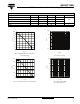
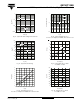
GB75YF120N Vishay High Power Products IGBT Fourpack Module, 75 A 160 20 VGE = 18V VGE = 15V VGE = 12V VGE = 9V 140 120 VCE (V) 100 ICE (A) 16 ICE = 75A ICE = 50A 14 ICE = 25A 18 80 60 12 10 8 6 40 4 20 2 0 0 0 1 2 3 4 5 7 6 9 11 19 20 VGE = 18V VGE = 15V VGE = 12V VGE = 9V ICE = 75A ICE = 50A 18 16 ICE = 25A 14 VCE (V) 100 ICE (A) 17 Fig. 8 - Typical VCE vs. VGE TJ = 25 °C 160 120 15 VGE (V) VCE (V) Fig.
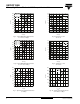
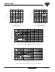
GB75YF120N IGBT Fourpack Module, 75 A Vishay High Power Products 1 1 tdOFF Switching Time (µs) TJ = 125°C ICES (mA) 0.1 0.01 tdON tF 0.1 tR TJ = 25°C 0.001 0.01 400 600 800 1000 1200 20 40 60 80 100 120 140 160 VCES (V) IC (A) Fig. 11 - Typical Zero Gate Voltage Collector Current Fig. 14 - Typical Switching Time vs. IC TJ = 125 °C; L = 200 µH; VCE = 600 V, RG= 5 Ω; VGE = 15 V 5.5 12 5 10 TJ = 25°C 4.5 125°C IRR (A) Vgeth (V) 8 4 TJ = 125°C 3.5 6 4 3 25°C 2 2.
GB75YF120N Vishay High Power Products IGBT Fourpack Module, 75 A 16 1600 14 125°C 1200 12 1000 10 VGE (V) QRR (nC) 1400 800 typical value 8 6 600 4 400 25°C 2 200 0 0 0 20 40 60 80 100 0 100 200 300 400 500 600 700 dIF/ dt (A/µs) QG, Total Gate Charge (nC) Fig. 17 - Typical Diode Qrr vs. dIF/dt VCC = 600 V; IF = 50 A Fig. 18 - Typical Gate Charge vs. VGE ICE = 5.0 A; L = 600 µH 1 Thermal Response (ZthJC ) D = 0.50 0.20 0.1 0.10 0.05 0.01 0.02 0.01 0.
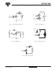
GB75YF120N IGBT Fourpack Module, 75 A Vishay High Power Products Driver L D.U.T. 0 + VCC - D + C - 1K 900 V D.U.T. Fig. C.T.1 - Gate Charge Circuit (Turn-Off) Fig. C.T.3 - S.C. SOA Circuit L Diode clamp/ D.U.T. + - 80 V L + - -5V D.U.T. D.U.T./ Driver 1000 V Rg + VCC Rg Fig. C.T.2 - RBSOA Circuit Fig. C.T.4 - Switching Loss Circuit R= D.U.T. VCC ICM + VCC Rg Fig. C.T.
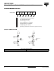
GB75YF120N Vishay High Power Products IGBT Fourpack Module, 75 A ORDERING INFORMATION TABLE Device code G B 75 Y F 120 N 1 2 3 4 5 6 7 1 - Insulated gate bipolar transistor (IGBT) 2 - B = IGBT Generation 5 NPT 3 - Current rating (75 = 75 A) 4 - Circuit configuration (Y = Fourpack) 5 - Package indicator (F = ECONO2) 6 - Voltage rating (120 = 1200 V) 7 - Speed/type (ultrafast with reduced diode, speed 8 to 60 kHz) CIRCUIT CONFIGURATION 21, 22 48, 49 40 28 41 29 15, 16
Legal Disclaimer Notice Vishay Disclaimer All product specifications and data are subject to change without notice. Vishay Intertechnology, Inc., its affiliates, agents, and employees, and all persons acting on its or their behalf (collectively, “Vishay”), disclaim any and all liability for any errors, inaccuracies or incompleteness contained herein or in any other disclosure relating to any product.