6121 Baker Road, Suite 108 Minnetonka, MN 55345 Phone (952) 933-6190 Fax (952) 933-6223 1-800-274-4284 www.chtechnology.com Thank you for downloading this document from C&H Technology, Inc. Please contact the C&H Technology team for the following questions - Technical Application Assembly Availability Pricing Phone – 1-800-274-4284 E-Mail – sales@chtechnology.com www.chtechnology.com - SPECIALISTS IN POWER ELECTRONIC COMPONENTS AND ASSEMBLIES - www.chtechnology.
GB75YF120UT www.vishay.com Vishay Semiconductors IGBT Fourpack Module, 75 A FEATURES • Square RBSOA • HEXFRED® low Qrr, low switching energy • Positive VCE(on) temperature coefficient • Copper baseplate • Low stray inductance design • Speed 8 kHz to 60 kHz • Material categorization: For definitions of compliance please see www.vishay.
GB75YF120UT www.vishay.com Vishay Semiconductors ELECTRICAL SPECIFICATIONS (TJ = 25 °C unless otherwise specified) PARAMETER Collector to emitter breakdown voltage SYMBOL VBR(CES) Collector to emitter voltage VCE(ON) Gate threshold voltage VGE(th) TEST CONDITIONS VGE = 0 V, IC = 500 μA Zero gate voltage collector current VGE(th)/TJ ICES Diode forward voltage drop VFM Gate to emitter leakage current IGES TYP. MAX. - - IC = 75 A, VGE = 15 V - 3.4 4.0 IC = 100 A, VGE = 15 V - 3.8 4.
GB75YF120UT www.vishay.com Vishay Semiconductors THERMISTOR ELECTRICAL SPECIFICATIONS (TJ = 25 °C unless otherwise specified) PARAMETER SYMBOL Resistance R25 B value B TEST CONDITIONS MIN. TYP. MAX. 4538 5000 5495 TJ = 100 °C 468.6 493.3 518 TJ = 25 °C/50 °C 3307 3375 3443 UNITS °K THERMAL AND MECHANICAL SPECIFICATIONS PARAMETER SYMBOL Junction to case IGBT Junction to case DIODE Case to sink, flat, greased surface MIN. TYP. MAX. UNITS RthJC (IGBT) - - 0.
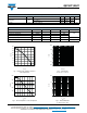
GB75YF120UT www.vishay.com 160 Vishay Semiconductors 20 VGE = 18V VGE = 15V VGE = 12V VGE = 9V 140 120 VCE (V) 100 ICE (A) 16 ICE = 75A ICE = 50A 14 ICE = 25A 18 80 60 12 10 8 6 40 4 20 2 0 0 0 1 2 3 4 5 7 6 9 11 15 17 19 VGE (V) VCE (V) Fig. 5 - Typical IGBT Output Characteristics TJ = 25 °C; tp = 500 μs Fig. 8 - Typical VCE vs.
GB75YF120UT www.vishay.com Vishay Semiconductors 1000 1 tdOFF Switching Time (ns) TJ = 125°C ICES (mA) 0.1 0.01 tdON tF 100 tR TJ = 25°C 10 0.001 400 600 800 1000 20 1200 30 40 50 Fig. 11 - Typical Zero Gate Voltage Collector Current 80 Fig. 14 - Typical Switching Time vs. IC TJ = 125 °C; L = 500 μH; VCC = 600 V, Rg = 5 ; VGE = 15 V 5.5 14000 5 12000 TJ = 25°C 4.5 10000 Energy (μJ) Vgeth (V) 70 IC (A) VCES (V) 4 TJ = 125°C 3.5 8000 EON 6000 3 4000 2.
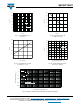
GB75YF120UT www.vishay.com Vishay Semiconductors 100 120 100 80 5 ohm 60 IRR (A) IRR (A) 80 60 27 ohm 40 40 20 47 ohm 20 0 0 10 15 20 25 30 35 40 45 50 55 60 65 70 75 80 0 10 20 30 40 50 RG (Ω) IF (A) Fig. 19 - Typical Diode IRR vs. Rg TJ = 125 °C; IF = 75 A Fig. 17 - Typical Diode IRR vs.
GB75YF120UT www.vishay.com Vishay Semiconductors Driver L + VCC - D.U.T. 0 D + C - 1K 900 V D.U.T. Fig. 22 - Gate Charge Circuit (Turn-Off) Fig. 24 - S.C. SOA Circuit L Diode clamp/ D.U.T. + - 80 V L + - -5V D.U.T. D.U.T./ Driver 1000 V Rg + VCC Rg Fig. 23 - RBSOA Circuit Fig. 25 - Switching Loss Circuit R= VCC ICM D.U.T. + VCC Rg Fig. 26 - Resistive Load Circuit Revision: 21-Mar-13 Document Number: 93172 7 For technical questions within your region: DiodesAmericas@vishay.
GB75YF120UT www.vishay.
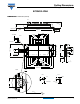
Outline Dimensions Vishay Semiconductors ECONO2 4PAK DIMENSIONS in millimeters (inches) Z Y 20.5 13.2 ± 0.15 1.25 0.8 - 0.02 - 0.06 105 ± 0.1 34.29 30.48 34.29 30.48 26.67 22.86 22.86 19.05 19.05 11.43 11.43 7.62 7.62 X 2:1 0.8 ± 0.03 3.81 21 ± 0.03 21 22 49 48 2 4 5 6 7 8 10 12 15 16 17 19 7.62 7.62 47 46 10.5 5.5 ± 0.05 11.43 11.43 33 32 30 29282726 42 ± 0.15 38 373635 21 ± 0.03 4140 23 24 4443 45.4 ± 0.2 + 1.0 - 0.5 7.62 7.62 11.43 15.24 19.05 22.86 30.48 39.49 19.05 22.
Legal Disclaimer Notice www.vishay.com Vishay Disclaimer ALL PRODUCT, PRODUCT SPECIFICATIONS AND DATA ARE SUBJECT TO CHANGE WITHOUT NOTICE TO IMPROVE RELIABILITY, FUNCTION OR DESIGN OR OTHERWISE. Vishay Intertechnology, Inc., its affiliates, agents, and employees, and all persons acting on its or their behalf (collectively, “Vishay”), disclaim any and all liability for any errors, inaccuracies or incompleteness contained in any datasheet or in any other disclosure relating to any product.