
User Manual


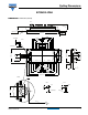

GB75YF120UT
www.vishay.com
Vishay Semiconductors
Revision: 21-Mar-13
1
Document Number: 93172
For technical questions within your region: DiodesAmericas@vishay.com
, DiodesAsia@vishay.com, DiodesEurope@vishay.com
THIS DOCUMENT IS SUBJECT TO CHANGE WITHOUT NOTICE. THE PRODUCTS DESCRIBED HEREIN AND THIS DOCUMENT
ARE SUBJECT TO SPECIFIC DISCLAIMERS, SET FORTH AT www.vishay.com/doc?91000
IGBT Fourpack Module, 75 A
FEATURES
•Square RBSOA
•HEXFRED
®
low Q
rr
, low switching energy
• Positive V
CE(on)
temperature coefficient
• Copper baseplate
• Low stray inductance design
• Speed 8 kHz to 60 kHz
• Material categorization: For definitions of compliance
please see www.vishay.com/doc?99912
BENEFITS
• Benchmark efficiency for SMPS appreciation in particular
HF welding
• Rugged transient performance
• Low EMI, requires less snubbing
• Direct mounting to heatsink space saving
• PCB solderable terminals
• Low junction to case thermal resistance
PRODUCT SUMMARY
V
CES
1200 V
I
C
at T
C
= 67 °C 75 A
V
CE(on)
(typical) 3.4 V
ECONO2 4PACK
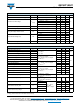
ABSOLUTE MAXIMUM RATINGS
PARAMETER SYMBOL TEST CONDITIONS MAX. UNITS
Collector to emitter voltage V
CES
1200 V
Continuous collector current I
C
T
C
= 25 °C 100
A
T
C
= 80 °C 67
Pulsed collector current
See fig. C.T.5
I
CM
200
Clamped inductive load current I
LM
200
Diode continuous forward current I
F
T
C
= 25 °C 60
T
C
= 80 °C 40
Diode maximum forward current I
FM
150
Gate to emitter voltage V
GE
± 20 V
Maximum power dissipation (IGBT) P
D
T
C
= 25 °C 480
W
T
C
= 80 °C 270
Maximum operating junction temperature T
J
150
°C
Storage temperature range T
Stg
- 40 to + 125
Isolation voltage V
ISOL
AC 2500 (min) V