
Instruction Manual

VSKT320PbF Series
www.vishay.com
Vishay Semiconductors
Revision: 05-Jul-12
5
Document Number: 94085
For technical questions within your region: DiodesAmericas@vishay.com
, DiodesAsia@vishay.com, DiodesEurope@vishay.com
THIS DOCUMENT IS SUBJECT TO CHANGE WITHOUT NOTICE. THE PRODUCTS DESCRIBED HEREIN AND THIS DOCUMENT
ARE SUBJECT TO SPECIFIC DISCLAIMERS, SET FORTH AT www.vishay.com/doc?91000
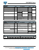
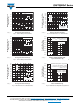
Fig. 7 - On-State Voltage Drop Characteristics
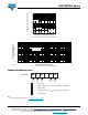
Fig. 8 - Thermal Impedance Z
thJC
Characteristics
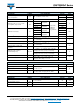
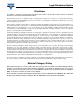
ORDERING INFORMATION TABLE
Note
• To order the optional hardware go to www.vishay.com/doc?95172
Instantaneous On-State Current (A)
Instantaneous On-State Voltage (V)
1.5 2.5 3.5
4.5
0.5
94085_07
10 000
1000
100
T
J
= 25 °C
T
J
= 130 °C
Per junction
0.001
0.1
0.01
1
0.001 0.01 0.1 100110
Square Wave Pulse Duration (s)
Z
thJC
- Transient Thermal
Impedance (°C/W)
94085_08
Steady state value
R
thJC
= 0.125 K/W
(DC operation)
1
- Module type
2 - Circuit configuration: T = Two SCR doubler configuration
3
- Current rating
4 - Voltage code x 100 = V
RRM
(see Voltage Ratings table)
5
- Lead (Pb)-free
Device code
51 32 4
VSK T 320 - 16 PbF